Subsections of Tutorials

Workbench Community

Installing Actifsource

Learn how to install the Actifsource Plugin for Eclipse and how to activate your license. more…

Simple Service

Learn to design a generic domain, write code templates and generate code. more…

Complex Service

Develop complex templates with template interdependencies. Use Java Functions from within templates. more…

State Machine

Develop a fully typed state machine model. Learn about decorating relations and range restrictions to ease the use of the specific domain model. more…

Language

Enabling syntax highlighting for any programming language more…

Literal Aspect

Writing Java validation aspects for user defined literal types. more…

Refactoring

Writing an aspect for refactoring model instances based on meta model changes. more…

Built-in Models

Learn how to create an eclipse plugin containing an Actifsource builtin model. more…

JavaListFunction

Learn about JavaListFunctions. Create your own JavaListFunction to sort resources. more…

Subsections of Workbench Community

Installing Actifsource

logo-large

Tutorial Actifsource Tutorial – Installing Actifsource
Required Time - 10 Minutes
Prerequisites - Download and install Java
- Download and install Eclipse
Goal - Installing actifsource as a Eclipse Plugin
Topics covered - Install the actifsource Plugin
- Switch to the actifsource Perspective
Notation $\hookrightarrow$ To do
$\hookrightarrow$ Information
Bold: Terms from actifsource or other technologies and tools
Bold underlined: actifsource Resources
Monospaced: User input
Italics: Important terms in current situation
Disclaimer The authors do not accept any liability arising out of the application or use of any information or equipment described herein. The information contained within this document is by its very nature incomplete. Therefore the authors accept no responsibility for the precise accuracy of the documentation contained herein. It should be used rather as a guide and starting point.
Contact Actifsource AG
Täfernstrasse 37
5405 Baden-Dättwil
Switzerland
www.actifsource.com
Trademark Actifsource is a registered trademark of Actifsource AG in Switzerland, the EU, USA, and China. other names appearing on the site may be trademarks of their respective owners.

Overview

Part I Preparation

  • Download Java from www.oracle.com.We recommend installing at least version 17. Alternatively, you can use OpenJDK.You can also skip this step if you optionally download the JRE via the Eclipse installer
  • Install Java on your desktop computer
  • Start by downloading Eclipse Installer from www.eclipse.org/downloads
  • Now go to File Explorer and click on Downloads after that click on the eclipse-inst-jre-win64.exe file for installing Eclipse IDE.
  • Select the installation version “Eclipse IDE for Eclipse Committers”

Part II Install the Actifsource Plugin

  • Actifsource is realized as an Eclipse Plugin

  • For more information about eclipse see also wikipedia (Eclipse (software))

    Install New Software Install New Software

  • From the menu Help select Install New Software...

    Install New Software.svg Install New Software.svg

  • Click Add...

  • Enter Name: actifsource

  • Enter Location: https://www.actifsource.com/updates or the given update site

  • Click OK

Install New Software Install New Software

  • Select actifsource
  • Click Next

Install New Software Install New Software

  • Click Next

Install New Software Install New Software

  • Carefully read the license agreement
  • If you agree, select I accept the terms of the license agreement
  • Click Finish

Install New Software Install New Software

  • Click Yes to restart Eclipse

Part III Switch to the Actifsource Perspective

Actifsource Perspective Actifsource Perspective

  • Click on the Open Perspective tool in the Eclipse toolbar
  • Click Other...

Actifsource Perspective Actifsource Perspective

  • Select the actifsource perspective
  • Click OK

actifsource-point-large

Simple Service

logo-large

Tutorial Actifsource Tutorial – Simple Service
Required Time • 70 Minutes
Prerequisites • Actifsource Tutorial – Installing Actifsource
Goal • Developing a generic domain model for a simple service infrastructure
• Instantiating specific domain objects according to the generic domain
• Writing code templates according to the generic domain
• Generate code for every specific domain object
Topics covered • Creating a new actifsource project
• Working with Diagram/Resource and Template Editor
• Generating Code
Notation ↪ To do
ⓘ Information
Bold: Terms from actifsource or other technologies and tools
Bold underlined: actifsource Resources
Monospaced: User input
Italics: Important terms in current situation
Disclaimer The authors do not accept any liability arising out of the application or use of any information or equipment described herein. The information contained within this document is by its very nature incomplete. Therefore the authors accept no responsibility for the precise accuracy of the documentation contained herein. It should be used rather as a guide and starting point.
Contact Actifsource AG
Täfernstrasse 37
5405 Baden-Dättwil
Switzerland
www.actifsource.com
Trademark Actifsource is a registered trademark of Actifsource AG in Switzerland, the EU, USA, and China. Other names appearing on the site may be trademarks of their respective owners.
Compatibility Created with actifsource Version 5.8.5

Overview

  • Create a new actifsource Project
  • Structure your models using Packages
  • Create Domain Classes in a Generic Domain Model for a Simple Service Infrastructure consisting of Services, Service-Calls, Arguments and Types:

overview-1 overview-1

  • Create a Specific Domain Model using your own domain-specific type system
  • Use Content Assist to create new domain-specific types or insert existing domain-objects

overview-2 overview-2


Part I: Create a new actifsource Project

  • Enable the actifsource perspective
  • Create and setup a new actifsource project “SimpleService”
  • Familiarize yourself with the basic structure of an actifsource project

Create a new actifsource Project

part1-1 part1-1

↪ Install Actifsource as a plugin from www.actifsource.com/
↪ Open the actifsource Perspective

part1-2 part1-2

↪ In the Open Perspective dialog click on Actifsource
↪ Click OK to confirm.

part1-3 part1-3

ⓘ Make sure the actifsource Perspective is activated


Create and Setup a new actifsource Project “SimpleService”

part1-4 part1-4

↪ Create a new actifsource Project

part1-5 part1-5

↪ Choose the project’s name com.actifsource.simpleservice
↪ Click Next

part1-6 part1-6

Info
  • In Actifsource, artifacts are called Resources
  • Resources are placed in folders and files
  • The default resource folder is called asrc

part1-7 part1-7

↪ Switch to the tab Target Folders
↪ Click Add Target Folder…

Info
  • Note: Generated Code is placed in target folders
  • Change project settings anytime using the project properties: Project/Properties/actifsource

part1-8 part1-8

part1-9 part1-9

↪ Add a target folder named src

part1-10 part1-10

Click Finish

part1-11 part1-11

Info
  • We have created a new actifsource Project named com.actifsource.simpleservice
  • Resource Folder asrc is where we place all actifsource Resources
  • Target Folder src is where the generated code is placed

Part II: Create a Generic Domain Model

  • Setup an appropriate package structure
  • Create a new diagram to model the generic domain model using generic classes and relations

Setup an Appropriate Package Structure

part2-1 part2-1

Info
  • In actifsource, Resources are organized within Packages

↪ Create a new Package in the resource folder asrc

part2-2 part2-2

↪ Name your package com.actifsource.simpleservice.generic as shown above
↪ Click Finish

Create a new Diagram to Model the Generic Domain Model

part2-3 part2-3

↪ Change the style for Package Presentation as you like

part2-4 part2-4

↪ Start with a Class Diagram of your generic domain model
↪ Create a new Class Diagram in the Package generic

part2-4 part2-4

↪ Name your Diagram ServiceDesign
↪ Click Finish


Add Generic Classes

part2-6 part2-6

Info
  • The Diagram ServiceDesign is opened in the Diagram Editor

↪ Insert the following Classes using the New Class Tool from the Palette: Service, Call, Parameter and Type


Add Generic Relations

part2-7 part2-7

↪ Specify the Relations between your Classes using the Relation Tool from the Palette on the right
↪ First, link Service and Call by clicking on Service and then on Call in the diagram


Composition Relations

part2-8 part2-8

Info
  • Actifsource distinguishes basically Composition, Aggregation and Association, all other relation types based upon them.
  • Composition and Aggregation resources live within the context of their owner
  • Association resources have their own lifetime and are referenced only
  • A Call is owned by Service because no Call must exist without its Service
  • Default name call is fine here

↪ Select the Composition

part2-9 part2-9

↪ Insert another Composition between Call and Parameter


Association Relations

part2-10 part2-10

Info
  • Type is used by Parameter because types have their own lifetime independent from referencing parameters

↪ Insert a Association between Parameter and Type

part2-11 part2-11

part2-12 part2-12

Info
  • Call should support a return type

↪ Insert a Association between Call and Type

part2-11 part2-11

part2-13 part2-13

↪ Name the relation returnType
↪ Choose SubjectCardinality 1..1 since we always want a return type in this example
↪ Click Ok


Adjust Cardinalities

part2-14 part2-14

Info
  • You can open the actifsource Resource Editor on any Actifsource resource by left-clicking on the desired resource while holding down the Ctrl-Key (Ctrl+ Left-Click)
  • Use the Cmd-Key on Apple computers

↪ Adjust the subjectCardinality of the call Relation

part2-15 part2-15

↪ Change the subjectCardinality from Cardinality0_N to Cardinality1_N
↪ Use Content Assist (Ctrl+Space) and select the desired Cardinality

part2-16 part2-16

↪ Make sure to change all marked cardinalities as shown above
↪ Choose subjectCardinality Cardinality1_1 for the relations type and returnType


Part III: Create a Specific Domain Model

  • Create a package to store specific classes
  • Create specific domain objects based on the generic domain model

Create a Package to Store Specific Domain Objects

part3-1 part3-1

↪ Create a new Package specific in simpleservice

Create Specific Domain Objects

part3-2 part3-2

↪ Select the Package specific
↪ Use the New Resource Tool to create a Resource of type Service

part3-3 part3-3

↪ Name the Service Patient
↪ Click Finish

Info
  • Being Subclass of NamedResource provides Patient with an Attribute name

part3-4 part3-4

Info
  • The Resource Patient of type Service has been created
  • The validator constantly checks all resources against the model
  • Since we decided a Service must have 1..N Call resources by selecting the subjectCardinality Cardinality1_N, the validator detects the incorrect subject cardinality and flags an error

part3-5 part3-5

↪ Use the context menu on the Relation call to explore your options
↪ Press Enter to create a Resource of type Call for the Patient Service

part3-6 part3-6

Info
  • The validator tells you that the created Call is missing a name and the returnType

part3-7 part3-7

↪ Enter the name Create by pressing enter on name or use the context menu
↪ Enter a new Parameter by pressing enter on parameter or use the context menu
↪ Enter the name LastName of the created Parameter

Info
  • Type and returnType are still missing

part3-18 part3-18

Info
  • So far there is no Resource of type Type
  • Type of Parameter LastName shall be String

↪ Activate Content Assist (Ctrl+Space) to insert a Resource of type Type
↪ Create a new Type String using Content Assist (Ctrl+Space)

part3-8 part3-8

↪ Name the new Type String
↪ Switch back to the Service Patient by clicking the Patient Tab or by pressing Alt+Left to navigate to the last edit location

part3-9 part3-9

Info
  • The created Type String is inserted automatically

part3-10 part3-10

↪ Select parameter
↪ Insert a new Parameter using Insert After (Ctrl+Enter) or Insert Before (Alt+Shift+Enter)

Info
  • You may rearrange the resources as you see fit using Move Up (Alt+Up) or Move Down (Alt+Down)

part3-11 part3-11

↪ Name the Parameter FirstName
↪ Insert the already created Type String using Content Assist (Ctrl+Space)

part3-12 part3-12

↪ For returnType create a new Type int using Content Assist (Ctrl+Space)

Info
  • The validator reports no more Model Inconsistencies

part3-13 part3-13

↪ Select call
↪ Insert a new Call using Insert After (Ctrl+Enter) or Insert Before (Alt+Shift+Enter)

Info
  • You may rearrange the resources using Move Up (Alt+Up) or Move Down (Alt+Down)

part3-14 part3-14

↪ Edit the Call Delete as shown above
↪ Insert Parameter Id of Type int
↪ Insert returnType boolean

part3-15 part3-15

Info
  • New resources are created in the same Package as they are referenced

↪ Create a new Package types in generic
↪ Move the Types boolean, int and String into the Package types using drag & drop

part3-16 part3-16

↪ Activate Link with Editor alt >< alt >< to link the Project Explorer with the editor

Info
  • Notice that types can still be located by Ctrl+Mouse-Left-Click on any type in the Resource Editor

Part IV: Use Code Templates to Generate Specific Code

  • Create a generator template
  • Enable Java functions for templates
  • Write generic code based on the generic domain model and generate code on the fly

Create a Generator Template

part4-1 part4-1

Info
  • Code Templates are also Resources in Actifsource
  • Like any Resource, a Template is located in a Package

↪ Create a new Package template in simpleservice

part4-2 part4-2

Info
  • Let’s write template code for any Service

↪ Select the Resource Service
↪ Choose New Template from the context menu

part4-3 part4-3

↪ Choose the Package template using Content Assist (Ctrl+Space)

Info
  • You might use just the first letters to select your packages

part4-4 part4-4

↪ Name the template ServiceImpl
↪ Click Finish


Write Generic Code Based on the Generic Domain Model

part4-5 part4-5

Info
  • Note: The Actifsource Template Editor is a text editor
  • Writing a template for Service means that any specific information on services comes from the specific domain model
  • The generic filename must contain a Variable to be unique for any specific Service

part4-6 part4-6

↪ Place the cursor on the Filename Line
↪ Use Content Assist (Ctrl+Space) to insert a Variable
↪ Choose the Resource Service

part4-7 part4-7

↪ Press ‘. ’ (dot) after Service
Content Assist opens automatically.
↪ Press Ctrl+Space to reopen Content Assist manually
↪ Select the Attribut name for Service

part4-8 part4-8

↪ Add the postfix Impl to the file name
↪ Add the language extension .java to the file name
↪ Save the file → a new file in your Target Folder src is created

Info
  • Note that syntax highlighting is automatically activated based on the file extension

part4-9 part4-9

Info
  • The orange bar on the left hand side is called main context
  • All text in the main context is generated for every specific Resource of type Service

↪ Write a Java Class as shown above. Make sure the class name contains the Variable Service.name
↪ Use Content Assist (Ctrl+Space) to insert the Variable
↪ Or use Copy/Paste (Ctrl+C/Ctrl+V) to copy the class name from file name
↪ Save the file (Ctrl+S) → Generated code can be found in the target folder src

part4-10 part4-10

Info
  • Let’s create a function for every Call in the Service

↪ Place the cursor in the class body
↪ Use the tool Insert Line Context (Alt+Insert) from the tool bar

part4-11 part4-11

Info
  • A new Line Context has been created
  • All text in the Sub Context shall be generated for every Resource of type Call in this Service

↪ Attach the Sub Context to the Parent Context using the Selector
↪ The given Selector must therefore navigate from Service to Call using Service.call
↪ Use Content Assist (Ctrl+Space) to specify the Selector
↪ Press Enter in the Selector to return to code

part4-12 part4-12

↪ Write a function in the Call Context as shown above

Info
  • The context grows as used
  • Save the file (Ctrl+S). The generated file should contain a class and its methods. Tip: Add another Service/Call.

part4-13 part4-13

Info
  • Let’s create a Java parameter for every Parameter in the Call

↪ Place cursor between the brackets
↪ Use the tool Insert Column Context (Alt+Shift+Insert) from the tool bar

part4-14 part4-14

↪ Write a parameter list in the Parameter Context as shown above
↪ Don’t forget the ‘, ’ (Comma) at the end
↪ Save the file (Ctrl+S). The generated file should contain a Java class , its methods and parameters

Info
  • Note that all text in the Parameter Context shall be generated
  • For that reason, there is a superfluous comma at the end of the last Parameter

part4-15 part4-15

Info
  • Single characters, but even lines, can be marked with Attributes
  • First (Alt+1) → Applied for the first iteration of the Context
  • Not First (Alt+2) → Applied for any iterations of the Context but the first
  • Not Last (Alt+3) → Applied for any iterations of the Context but the last
  • Last (Alt+4) → Applied for the last iteration of the Context
  • Empty (Alt+5) → Applied if Context is never iterated

part4-16 part4-16

Info
  • The comma has to be written after each Parameter except after the last one

↪ Select both the comma and the following space
↪ Choose Not Last (Alt+3) from the tool bar
↪ Save the file (Ctrl+S). The generated file should contain a class , its methods and parameters

Info
  • No superfluous comma is generated this time

part4-17 part4-17

Info
  • Let’s write specific code for the generated functions

↪ Place cursor in the function body
↪ Insert a Protected Context in the function body with the tool shown above

part4-18 part4-18

↪ Write any text in the Protected Context, e.g. a TODO comment

Info

Note that Call is translated in Call. Tip: Rename Call to ServiceCall to find out why this makes sense

↪ Write specific code within the Protected Regions of the generated files
Info

You must not delete the Tags Begin Protected Region and End Protected Region

Tip

Alter the template code. Save the template. See what happens with the Protected Regions


actifsource-point-large

Complex Service

logo-large

Tutorial Actifsource Tutorial – Complex Service
Required Time - 60 Minutes
Prerequisites - Actifsource Tutorial – Installing Actifsource
- Actifsource Tutorial – Simple Service
Goal - Use Java Functions to reuse text fragments in your templates and capture complex expressions to keep your templates clean and easy to read

- Use Function Spaces to keep Java Functions organized
Topics covered - - Extracting Java Functions from template code
- Editing Java Functions
- Advanced Template Editor Context Operations
- Functions Spaces and Template Functions
- Built-in Java Functions
- Place generated code in specific folders
- Copy with Context
Notation ↪ To do
ⓘ Information
Bold: Terms from actifsource or other technologies and tools
Bold underlined: actifsource Resources
Monospaced: User input
Italics: Important terms in current situation
Disclaimer The authors do not accept any liability arising out of the application or use of any information or equipment described herein. The information contained within this document is by its very nature incomplete. Therefore the authors accept no responsibility for the precise accuracy of the documentation contained herein. It should be used rather as a guide and starting point.
Contact Actifsource AG
Täfernstrasse 37
5405 Baden-Dättwil
Switzerland
www.actifsource.com
Trademark Actifsource is a registered trademark of Actifsource AG in Switzerland, the EU, USA, and China. other names appearing on the site may be trademarks of their respective owners.

Overview

  • Prepare a new actifsource Project as seen in the Actifsource Tutorial – Simple Service

  • Learn how to extract Java Functions from template code to cope with complex situations
    image2 image2

  • Edit Java Functions

  • Learn about advanced Context Operations in the Template Editor

  • Learn about Function Spaces and how to place functions

  • Use built-in functions
    image3 image3

  • Generate code for specific folders

  • Copy template code with its Context

Part I: Preparation

  • Prepare a new actifsource Project as seen in the Actifsource Tutorial – Simple Service

    • Setup the Target Folder src

    • Create a Generic Domain Model

    • Create a Specific Domain Model

    • Create a Code Template

  • Use the following package structure

image4 image4

Create a Generic Domain Model

image5 image5

  • Create a Generic Domain Model in the DiagramEditor named ServiceDesign in the Package generic

  • The Design shall contain the following Domain Classes

    • Service, Call, Parameter, Type
  • Insert a Composition between

    • Service and Call

    • Call and Parameter

  • Insert a Association between

    • Call and Type

    • Parameter and Type

  • Adjust the Cardinalities as shown above

Warning: The layout for the relations transition and targetState might differ in your editor

Create a Specific Domain Model

image6 image6

  • Create a Service named Patient in the Package specific

  • Add the Calls Create and Delete

  • Add the Parameter LastName, FirstName and Id as shown above

  • Add the returnTypes as shown above

image7 image7

  • Create a Code Template named ServiceImpl in the Package template

  • Write code as shown above

  • The function shall be placed in the Context Call Selector is Service.call

  • The function parameters shall be placed in the Context Parameter; Selector is Call.parameter

  • Save the Code Template

image8 image8

  • You’ll find the generated code PatientImpl.java in the Target Folder src

Part II: Java Functions

  • Use Java Functions to

    • extract recurring text fragments from your templates

    • capture complex expressions to keep your templates clean and easy to read

  • Use Java Classes generated from your Generic Domain Model to write and maintain complex Java Functions

Extract Function

image9 image9

  • We should extract identical terms to honor the DRY principle (Don’t Repeat Yourself)
Info

Note that the term Service.name_Impl is used twice

image10 image10

  • In your template select the text you want to extract into a function
  • The light bulb at the left hand indicates Quick Assist is available

image2 image2

  • Activate QuickAssist by clicking the light bulb or by pressing Ctrl+1
  • Click Extract JavaFunction

image11 image11

  • Name the function className
  • Click Finish

Using Function

image12 image12

  • The new function className returns the extracted fragment from your template
  • The static function className is added to the static Java class ServiceImpl.ServiceFunctions in class ServiceImpl; this class is automatically generated by actifsource
  • The term Service.name_Impl has been replaced by the function Service.className
  • Java Functions are shown in italics in the actifsource Template Editor

image13 image13

  • Let’s replace the second occurrence of the term Service.name_Impl
  • Use Content Assist (Ctrl+Space) on Service to insert the function className for your class name

image14 image14

  • Open the underlying Function Model (Ctrl+Alt+Left-Click)
  • Alternatively, you can use the Tool Open Link in JavaEditor from the actifsource Template Editor toolbar image15 image15

Editing Functions

image16 image16

  • Change function declaration here if needed
  • Please notice that the Function declaration was placed in the template

image17 image17

image14 image14

  • Open the underlying Java Function (Ctrl+Left-Click)
  • Alternatively, you can use the Tool Open Link in JavaEditor from the actifsource Template Editor toolbar image18 image18

image19 image19

  • The class ServiceImpl is opened in the Java Editor showing your function className

image20 image20

Info

Note that actifsource generates a select method for each property of the corresponding class in the Generic Domain Model. You may use these methods to traverse your Generic Domain Model using the respective selectPROPERTY() methods in your Java Functions

image21 image21

  • Make sure to place additional imports within the corresponding Protected Regions
  • Please note that all code outside Protected Regions will be overwritten if the respective source file is re-generated.

Part III Function Spaces

  • Function Declarations are managed as actifsource Resources
  • All Function Declarations are placed in Functions Spaces
  • Templates are Functions Spaces by default
  • Functions Spaces can exist without Templates
  • Function Spaces are Resources and can therefore be placed in Packages

Advanced Context Operations

image22 image22

  • Let’s add a new line after the Call Context in the Service Context
  • Place cursor on the last position of the Call Context
Info

Note that the corresponding Context Bar is highlighted

image23 image23

  • Press Cursor-Right
  • While the cursor stays at its position, the Service Context is now highlighted
  • Alternatively, you can use the context navigation from the actifsource Template Editor toolbar image24 image24

image25 image25

  • Press Enter
  • A new line has been added in the Parent Context

Add Context via Quick Assist

image26 image26

  • Let’s look at a quick and easy way to insert a new Context
  • Insert the Variable Service.call using Content Assist (Ctrl+Space)

image27 image27

  • The light bulb at the left hand indicates Quick Assist is available
  • Activate QuickAssist by clicking the light bulb or pressing Ctrl+1

image28 image28

  • Click on Create Line Context

image29 image29

  • The Variable Service.call has been replaced by Call
Info

Note that a new Call Context (Selector: Service.call) has been added

Built-In Functions

image3 image3

  • Let’s use Built-In Functions on Attributes
  • Press '.' (dot) and Content Assist (Ctrl+Space) after name to see all available Built-In Functions

image30 image30

  • Complete the member variable declaration as shown above

Extract Function in Function Space

image31 image31

  • Call.name_Impl shall be the name of a new Template
  • Select the term Call.name_Impl
  • Activate QuickAssist by clicking on the light bulb or pressing Ctrl+1
  • Click Extract TemplateFunction
  • Template Functions behave like templates and are easier to handle than Java functions

image32 image32

  • Name the function className
  • Click New Template to create a new template which acts as Function Space for the new function className
Info

Note that the default Function Space for this new function is the Template ServiceImpl

image33 image33

  • Check the Package
  • Name the Template CallImpl
  • Press Finish

image34 image34

  • Press Finish
Info

Note that the Function Space has been changed from ServiceImpl to CallImpl

image35 image35

  • The Term Call.name_Impl has been replaced by Call.className@CallImpl
  • className@CallImpl indicates that the Function className belongs to the Function Space CallImpl

image36 image36

  • A new Template named CallImpl has been created in the Package template
  • Use the Function className in the file line of your template
Info

Note that className is the Function which we extracted in the template ServiceImpl before

image37 image37

  • Write a simple class as shown above
  • Write a method execute with returnType and Parameter
  • Please notice that you might copy the whole parameter expression from the ServiceImpl Template
  • Place a Protected Context in the function body

Templates and Folders

image38 image38

  • Open the underlying Template Function for className (Ctrl+Left-Click)
  • Alternatively, you can use the Tool Open Link in JavaEditor from the actifsource Template Editor toolbar image18 image18

image39 image39

  • The function className is handled as a Template Function (partial template)
  • Template Functions are easy to handle
  • A TemplateFunction may call itself to follow recursive meta model designs (Composite Pattern)

image40 image40

  • Generated artifacts are placed in the Target Folder of your project

  • You may want to place generated artifacts in specific sub folders

  • Add Service.name/ as folder information in the file line of the Template ServiceImpl as shown above

image41 image41

  • We want all Call implementations to be generated in the same folder as their corresponding Service
  • Add Service.name as the folder name in the file line of the Template CallImpl as shown above
  • Save the Templates CallImpl and ServiceImpl
  • Protected Regions of the generated files are preserved image42 image42
Info
  • Note that files generated from this template are moved to the new location automatically

Copy with Context

image43 image43

  • Extract a TemplateLineFunction memberName for the member variable name

image44 image44

  • Also use the function memberName in the function body as shown above

image45 image45

  • Open the underlying TemplateLineFunction for memberName (Ctrl+Left-Click)
  • Alternatively, you can use the Tool Open Link in JavaEditor from the actifsource Template Editor toolbar image18 image18

image46 image46

  • The function className is handled as a TemplateLineFunction
  • Template Line Functions are the easiest way to reuse information
  • Template Line Functions do not allow context

image47 image47

  • We want to copy Parameter.name including the Parameter Context and the separating comma from the functions parameter list
  • Select the Term Parameter.name
  • From the Context Menu, select Copy with Context
  • From the Subcontext Menu, select Parameter
Info

Note also the shortcuts Alt+PageUp to select the parent context, and Ctrl+C to copy a context

image48 image48

  • Place your cursor between the brackets
  • Select Paste from the Context Menu (Ctrl+V)

image49 image49

  • The text and its corresponding context are inserted

actifsource-point-large

State Machine

logo-large

Tutorial Actifsource Tutorial – State Machine
Required Time - 40 Minutes
Prerequisites - Actifsource Tutorial – Installing Actifsource
- Actifsource Tutorial – Simple Service
- Actifsource Tutorial – Complex Service
Goal - Developing an easy to use state machine model
- Show possible events in every transition
- Restrict transition target to state instances of the own state machine
Topics covered - Decorating Relation Aspect
- Range Restriction Aspect
- Selector (forward and reverse selection)
Notation ↪ To do
ⓘ Information
Bold: Terms from actifsource or other technologies and tools
Bold underlined: actifsource Resources
Monospaced: User input
Italics: Important terms in current situation
Disclaimer The authors do not accept any liability arising out of the application or use of any information or equipment described herein. The information contained within this document is by its very nature incomplete. Therefore the authors accept no responsibility for the precise accuracy of the documentation contained herein. It should be used rather as a guide and starting point.
Contact Actifsource AG
Täfernstrasse 37
5405 Baden-Dättwil
Switzerland
www.actifsource.com
Trademark Actifsource is a registered trademark of Actifsource AG in Switzerland, the EU, USA, and China. other names appearing on the site may be trademarks of their respective owners.

Overview

image2 image2

  • Create a simple state machine

image3 image3

  • Show possible events in every transition

image4 image4

  • Restrict transition target to state instances of the own state machine

image5 image5

  • Write a code template to generate code for a statemachine

Part I Preparation

  • Prepare a new actifsource Project named ch.actifsource.tutorial.statemachine as seen in the Actifsource Tutorial Simple Service
  • Use the following package structure

image6 image6

Part II Create a State Machine

  • Create a simple state machine
  • Instantiate the state machine and see its deficits

Create a Generic State Machine Model

image7 image7

  • Create a Generic Domain Model named Design in the Package generic using the DiagramEditor
  • The Design shall contain the following Domain Classes
    • Statemachine Event State Transition

image8 image8

  • Insert a Composition between

    • Statemachine and Event
    • Statemachine and State
    • State and Transition
  • Insert a Association between

    • Transition and State
  • Adjust the Cardinalities as shown above

  • Warning: The layout for the relations transition and targetState might differ in your editor

Create a Specific State Machine

image9 image9

image10 image10

  • Create a Statemachine named Statemachine1 in the Package specific

image11 image11

  • Add the Events start and stop
  • Add the States Initialized Started and Stopped as shown above

Part III Decorating Relation Aspect

  • Learn how to decorate a relation with a list of resources in order to prevent the mixing of instances from different Statemachines

Add a Decorating Relation Aspect

image12 image12

  • In State open the Composition transition
  • Press Enter on aspect[DecoratingRelationAspect]

image13 image13

  • Select ResourceSelectorAspectImplementation
  • Click OK
Info

Note that you can choose between a JavaAspectImplementation and a SelectorAspectImplementation

  • Selecting the JavaAspectImplementation allows you to write Java Code for complex operations
  • Selecting the ResourceSelectorAspectImplementation allows you to use the easy Selector syntax

image14 image14

  • Let's look at a possible Transition for every Event
  • The Composition transition is found in State
  • We have to navigate from State to Event
    • Navigate backwards from State via state to Statemachine
    • Navigate forward from Statemachine via event to Event

image15 image15

  • Enter the Selector State.-state.event using Content Assist (Ctrl+Space)
Info

Note that State.–state navigates backwards from State to Statemachine

image16 image16

  • Implementing a DecoratingRelationAspect asks for a subclass of Decorator

  • Decorator has a useRelation target which is used to store the specific decorating Resource

    • Shown as: decoratingRelation[target]
  • Open Quick Assist by clicking the light bulb or press Ctrl+1

image17 image17

  • Use Quick Assist to let Transition extend Decorator

image18 image18

  • Open Transition
  • By default a Class extends NamedResource
  • The Quick Assist Action changed the extends statement from NamedResource to Decorator

image19 image19

  • Quick Assist has done the following
    • Added extend Decorator
    • Added Association event

image20 image20

  • The range of Decorator.target is Resource and therefore untyped in the context of your domain
  • The new Association target extends Decorator.target but with Event as its range
  • When writing template code, you are able to access Transition.event typed as Event

image21 image21

Info

Note that the Association target has been added in the Design Diagram automatically

Use the Decorating Relation Aspect

image22 image22

  • Open the specific Statemachine Statemachine1
  • Add new Events and observe the decoratingRelation transition
Info

Note there is a decoratingRelation transition for every Event

image23 image23

  • In the State Initialized create a new Transition for transition[start]
  • Select Started as targetState
Info

Note that the relation target has been completed automatically with the specific decorating Event start

image24 image24

  • Configure the State instances Started and Stopped as shown above

Part IV Range Restriction Aspect

  • Content Assist (Ctrl+Sapce) in actifsource shows all instances of a desired type; It is often useful to restrict this selection
  • Learn how to apply range restrictions to filter instances for a given type

Without Range Restriction

image25 image25

  • Let's discover the needs for a range restriction aspect
  • Create a Statemachine named Statemachine2 in the Package specific
  • Add the Event instances open and close
  • Add the States instances Initialize Opened and Closed

image26 image26

  • Create any new Transition
  • Use Content Assist (Ctrl+Space) to add a targetState of type State
Info

Note that all instances of State are listened instead of just the ones from Statemachine2

Add a Range Restriction Aspect

image27 image27

  • In Transition open the useRelation targetState

  • Press Enter on aspect[RangeRestrictionAspect]

image28 image28

  • Select ResourceSelectorAspectImplementation
  • Click OK
Info

Note that you can choose between a JavaAspectImplementation and a SelectorAspectImplementation

  • Selecting the JavaAspectImplementation allows you to write Java Code for complex operations
  • Selecting the ResourceSelectorAspectImplementation allows you to use the easy Selector syntax

image29 image29

  • Let's restrict the range of targetState to instances of States owned by the own Statemachine

  • The useRelation targetState is found in Transition

  • We have to navigate from Transition to all States of the Statemachine

    • Navigate backwards from Transition via transition to State
    • Navigate backwards from State via state to Statemachine
    • Navigate forward from Statemachine via state to State

image30 image30

  • Enter the Selector Transition.-transition.-state.state using Content Assist (Ctrl+Space)

Use the Range Restriction Aspect

image31 image31

  • Use Content Assist (Ctrl+Space) again to add the targetState Opened of type State
Info

Note that only instances of State from Statemachine2 are listed

image32 image32

  • Get familiar with Decorating Relations and Range Restrictions
  • Write an actifsource Code Template to generate a state machine

Part V Code Template for Statemachines

  • Write a code template for instances of Statemachine

Write a code template for Statemachines

image33 image33

  • Create a package ch.actifsource.tutorial.statemachine.template
  • Select the new package and choose New->Template from the context menu.

image34 image34

  • Insert StatemachineImpl as Template Name
  • Choose the Base Type ch.actifsource.tutorial.statemachine.generic.Statemachine
  • Click Finish

image35 image35

  • Insert Statemachine.name on the Filename Line and make sure that the language (C++) is automatically detected.
  • Write the skeleton for a class Statemachine.name

image36 image36

Next, we define an enumeration variable with the all the States of a Statemachine as enumerators. This variable stores the current state of a Statemachine

  • Write the declaration of enumeration variable m_aState
  • Insert a LineContext in the enumeration list and choose the Selector Statemachine.state with the support of the Content Assist
  • Insert State.name in the newly created LineContext. Append a ','. Then mark the ',' and select NotLast to make sure that there is no comma after the last entry in the enumeration list.

image37 image37

We define a member function for each event of our Statemachine which will later handle all the possible transitions triggered by the event:

  • Create a new LineContext and choose Statemachine.event as the selector of the line context
  • Write the skeleton of a function returning void named Event.name

image38 image38

We write a switch-statement with the current state m_aState as control variable and define a LineContext that iterates over all Transitions referring to an Event through the relation Transition.event

  • Create a switch-statement with the m_aState as control variable
  • Create a LineContext inside the switch-statement
  • Choose Event.-event as the Selector of the new LineContext

image39 image39

We create a LineContext that iterates over all States that refer to a Transition through the relation State.transition

  • Create a LineContext on the same line as LineContext that we have crated before
  • Choose Transition.-transition as the Selector of the new LineContext

image40 image40

We write a case-statement for each State that is (indirectly) referring to an Event through State.transition.event

  • Insert a case State.name and add a break at the end of the case-statement

image41 image41

We update the current state as follows: We first select for an Event the Transitions that refer to the Event trough Transition.event For each Transition we select the States that are connected to Transition by State.transition For each State it holds that if the current state m_aState is equal to State then the new State of the Statemachine is Transition.targetState

  • Write code to assign Transition.targetState.name to the variable m_aState

image42 image42

In order to generate code from the template we have implemented before, we setup the project properties for Actifsource:

  • Select the project ch.actifsource.tutorial.statemachine and choose Project->Properties from the main menu

image43 image43

  • In the Properties dialog choose Actifsource and select the tab Target Folders

image44 image44

  • In the dialog Select Target Folder, click on the button Create folder

image45 image45

  • Enter src as Folder Name in the New Folder dialog

  • Click on OK in the New Folder dialog and then in the Select Target Folder dialog

image46 image46

  • Check the settings on the Target Folders tab and close the dialog by clicking on OK

image47 image47

The code generator now applies the template StatemachineImpl to the two Statemachine instances and stores the resulting files to the src folder:

  • Open the src folder and check that the two files Statemachine1Impl.hpp and Statemachine2Impl.hpp have been generated
  • If the files have not been generated, make sure that Generate Automatically is active under Project in the main menu

image5 image5

  • Open the newly generated files and inspect and compare the code for the two Statemachines
  • Learn how to extend the Statemachine by conditional transitions and actions executed together with a transition by working through the Actifsource Tutorial Code Snippet
  • Complete the generated classes by adding a member function initialize()

actifsource-point-large

Language

logo-large

Tutorial Actifsource Tutorial – Language
Required Time - 15 Minutes
Prerequisites - Actifsource Tutorial – Installing Actifsource
- Actifsource Tutorial – Simple Service
Goal - Enabling syntax highlighting for any programming language
Topics covered - Create a new Language
- Use the new Language
Notation ↪ To do
ⓘ Information
Bold: Terms from actifsource or other technologies and tools
Bold underlined: actifsource Resources
Monospaced: User input
Italics: Important terms in current situation
Disclaimer The authors do not accept any liability arising out of the application or use of any information or equipment described herein. The information contained within this document is by its very nature incomplete. Therefore the authors accept no responsibility for the precise accuracy of the documentation contained herein. It should be used rather as a guide and starting point.
Contact Actifsource AG
Täfernstrasse 37
5405 Baden-Dättwil
Switzerland
www.actifsource.com
Trademark Actifsource is a registered trademark of Actifsource AG in Switzerland, the EU, USA, and China. other names appearing on the site may be trademarks of their respective owners.

Overview

  • Preparation
  • Create a new Language
  • Using the Language

Part I Preparation

image2 image2

  • Prepare a new actifsource Project named ch.actifsource.tutorial.language as seen in the Actifsource Tutorial Simple Service

Part II Create a new Language

  • Instances of Language describe the following language elements

    • Keywords
    • Single Line Comments
    • Multi Line Comment
    • Color and font type
  • Let’s create an new Language instance for a fictitious math language

image3 image3

  • Select the package language
  • Use the New Resource Tool to create a Resource of type Language

image4 image4

  • Name the Language Math

  • Click Finish

image5 image5

  • Define the file name extension for the new language
  • Define your keyword style: color DarkRed, fontModifier Bold
  • Define your keywords: var, add, sub, mul, div
  • Define your single line comment style: color DarkGreen, fontModifier Italic
  • Define your single line comment tag: #
  • Use a StringStyle to define string coloring

Part III Use the new Language

  • The actifsource template editor is now supporting the new Languagefor the specific file extensions
  • Let's test the new syntax highlighting

image6 image6

  • Create a new Template in the Package language

image7 image7

  • Name the Template Test
  • Click Finish
  • Ignore the warning “No build config selected.”

image8 image8

  • In the file line, choose the file extension .math
  • The Language is Math selected automatically
  • Use Content Assist (Ctrl+Space) to select the language manually (i.e. if there is no file extension)
  • Use Ctrl+Click on the Language to open the Language Resource

image9 image9

  • Add some Code using the new keywords
  • Try to write some comments

actifsource-point-large

Literal Aspect

logo-large

Tutorial Actifsource Tutorial – Literal Aspect
Required Time - 30 Minutes
Prerequisites - Actifsource Tutorial – Installing Actifsource
- Actifsource Tutorial – Simple Service
Goal - Writing an aspect for custom literal types
- Validate custom literals
Topics covered - Create a simple demo model
- Add a new Literal
- Implement the Literal Aspect
- Using the Literal Aspect
Notation ↪ To do
ⓘ Information
Bold: Terms from actifsource or other technologies and tools
Bold underlined: actifsource Resources
Monospaced: User input
Italics: Important terms in current situation
Disclaimer The authors do not accept any liability arising out of the application or use of any information or equipment described herein. The information contained within this document is by its very nature incomplete. Therefore the authors accept no responsibility for the precise accuracy of the documentation contained herein. It should be used rather as a guide and starting point.
Contact Actifsource AG
Täfernstrasse 37
5405 Baden-Dättwil
Switzerland
www.actifsource.com
Trademark Actifsource is a registered trademark of Actifsource AG in Switzerland, the EU, USA, and China. other names appearing on the site may be trademarks of their respective owners.

Overview

  • Create a simple demo model
  • Add a new Literal

image2 image2

  • Setup the project

image3 image3

  • Implement the Literal Aspect
  • Using the Literal Aspect

image4 image4

Part I Setup a simple demo model

  • Prepare a new actifsource Project as seen in the Actifsource Tutorial Simple Service with name and namespace ch.actifsource.tutorial.literal.aspect as shown in this tutorial

image5 image5

  • Create a new class as shown in the picture with name Component and one attribute
  • As you can see in the content assist, there is no Literal for representing a date.
  • Create a new Literal using the content assist

image2 image2

  • Set the name to DateLiteral
  • For the moment there is not much more we can do, since we first need to setup the project.

Part II Setup the project

image30 image30

  • First we need to to convert this project to a Eclipse Plugin Project
  • Right click on the project ch.actifsource.tutorial.literal.aspect in the navigator to open the context menu.
  • Go into the submenu Configure and click on Convert to Plug-in Projects…
Info

Note that eclipse allows a project to be an actifsource project and a Eclipse Plugin project at the same time.

image31 image31

  • Check the checkbox in front of ch.actifsource.tutorial.literal.aspect
  • Click Finish

image32 image32

  • This will convert the project however there will be some error and warning needed to be fixed.

image33 image33

  • Right click on the Actifsource classpath container
  • Go into the submenu Build Path and select Remove from Build Path

image34 image34

  • Open the MANIFEST.MF

image35 image35

  • Now you have a Plug-In project and need to set the dependencies to actifsource plugin defining the Literal Aspect. In this case it is the ch.actifsource.core"-Plug-In.
  • Add a dependency to the ch.actifsource.core" and the ch.actifsource.ui.refactoring-Plugin

image36 image36

  • Create a new java source folder for the aspect implementation.
  • We recommend naming the new source folder src
  • Click Finish

Part III Implement the Literal Aspect

  • After the project setup, we are ready to create a java class using an actifsource core interface
  • Java Class implementing the ch.actifsource.tutorial.literal.aspect.ILiteralAspect.

image11 image11

  • There are four methods to implement
  • getValueType The java type representing the literal value. In our case the java “Date” class.
  • getValue A conversion method to convert the literal value to an instance of the value type, which may return “null”, if the value is invalid
  • allowMultiLine True, to allow the use to type in multiple lines using line breaks
  • isValid Returning an error string if the value is invalid or “null” if valid
  • Implement the LiteralAspect as following
package ch.actifsource.tutorial.literal.aspect;

import java.text.DateFormat;
import java.text.ParseException;
import java.util.Date;
import java.util.Locale;

import javax.annotation.CheckForNull;


import ch.actifsource.core.INode;
import ch.actifsource.core.job.IReadJobExecutor;
import ch.actifsource.core.model.aspects.ILiteralAspect;
import ch.actifsource.core.scope.IResourceScope;

public class DateLiteral implements ILiteralAspect {

  @Override
  public boolean allowMultiline() {
    return false;
  }

  @Override
  public @CheckForNull Object getValue(IReadJobExecutor executor, IResourceScope arg1, INode value) {
    DateFormat dateInstance = DateFormat.getDateInstance(DateFormat.LONG, Locale.ENGLISH);
    try {
      return dateInstance.parse(value.toString());
    } catch (ParseException e) {
      return null;
    }
  }

  @Override
  public Class<?> getValueType() {
    return Date.class;
  }

  @Override
  public @CheckForNull String isValid(IReadJobExecutor executor, IResourceScope scope, String value) {
    DateFormat dateInstance = DateFormat.getDateInstance(DateFormat.LONG, Locale.ENGLISH);
    try {
      dateInstance.parse(value.toString());
      return null;
    } catch (ParseException e) {
      return e.getMessage();
    }
  }

}

Part IV Using the Literal Aspect

  • Go back to the “DateLiteral” and add new value for the aspect [LiteralAspect] relation.

image13 image13

  • Type “Date” and use the content assist to select the class.

image14 image14

  • The Literal is now ready to use, since we created the Literal early with the content assist, the attribute in the “Component” is already using it

image15 image15

image16 image16

  • To test the literal, just create a new instance of the “Component” and define a “releaseDate”.

image4 image4

actifsource-point-large

Refactoring

logo-large

Tutorial Actifsource Tutorial – Refactoring
Required Time - 45 Minutes
Prerequisites - Actifsource Tutorial – Installing Actifsource
- Actifsource Tutorial – Simple Service
Goal - Writing an aspect for refactoring instances
- Refactor instances to match the new specification literals
- Update templates
Topics covered - Create and register a refactoring aspect
- Update the simple service model
- Execute a refactoring
- Update the templates
Notation ↪ To do
ⓘ Information
Bold: Terms from actifsource or other technologies and tools
Bold underlined: actifsource Resources
Monospaced: User input
Italics: Important terms in current situation
Disclaimer The authors do not accept any liability arising out of the application or use of any information or equipment described herein. The information contained within this document is by its very nature incomplete. Therefore the authors accept no responsibility for the precise accuracy of the documentation contained herein. It should be used rather as a guide and starting point.
Contact Actifsource AG
Täfernstrasse 37
5405 Baden-Dättwil
Switzerland
www.actifsource.com
Trademark Actifsource is a registered trademark of Actifsource AG in Switzerland, the EU, USA, and China. other names appearing on the site may be trademarks of their respective owners.

Overview

  • Create and register a refactoring aspect

image2 image2

  • Update the simple service model

image3 image3

  • Write a simple refactoring

image4 image4

  • Execute the refactoring

image5 image5

  • Update the templates

image6 image6

Part I Create and register a refactoring aspect

Setup a project

image7 image7

  • Open the project created during the Actifsource Tutorial Simple Service or make an new one with the new project with name and namespace ch.actifsource.tutorial.refactoring as shown in this tutorial
  • Create a new Package with name refactoring
  • Create a Refactoring resource of type ch.actifsource.ui.refactoring.Refactoring with name Refactoring

image3 image3

  • You need to convert this project to a Eclipse Plugin Project
  • Right click on the project ch.actifsource.tutorial.builtin in the navigator to open the context menu.
  • Go into the submenu Configure and click on Convert to Plug-in Projects…

image4 image4

  • Check the checkbox in front of ch.actifsource.tutorial.refactoring
  • Click Finish

image5 image5

  • This will convert the project however there will be some error and warning needed to be fixed.

image6 image6

  • Right click on the Actifsource classpath container
  • Go into the submenu Build Path and select Remove from Build Path

Create and register a refactoring aspect

image8 image8

  • Open the MANIFEST.MF

image9 image9

  • Add a dependency to the ch.actifsource.core" and the ch.actifsource.ui.refactoring-Plugin

image10 image10

  • Create a new java source folder for the aspect implementation.

image11 image11

  • We recommend naming the new source folder src-aspect
  • Click Finish

image12 image12

  • Create a new java class extending the ch.actifsource.core.model.aspects.impl.AbstractRefactorerAspect class

image13 image13

  • Add the following constructor function to the class
public CallGroupRefactoringAspect() {
  super("1.0.0",
        Date.from(LocalDate.of(2024, 1, 6).atStartOfDay(ZoneId.systemDefault()).toInstant()),
        "Call to Callgroup");
}
  • The first parameter defines a version string for the aspect. The following three parameters are used to specify the date when the refactoring was written.The last parameter is the name. The arguments are shown in the dialog and used to sort the refactoring aspects.

image2 image2

  • Register the java class in the Refactoring instance

image14 image14

  • The result should look like above. There must be no more model inconsistencies be present.

Part II Update the simple service model

image15 image15

  • Open the Service class
  • Select the call relation and cut the resource by using the clipboard (Ctrl+X)

image16 image16

  • Create a new Relation named group with a new Class named “CallGroup” used as the range

image17 image17

  • Paste the call relation from the clipboard into the new Callgroup

image18 image18

  • Add an additional Attribute named async of type boolean with default value false
  • We only use an attribute to keep the tutorial simple. An alternative would be to create a subclass of CallGroup instead.

Part III Write a simple refactoring

Select project Properties Select project Properties

  • First we want to have more convenient access to the resource guids.
  • To accomplish this, we need to check a setting in the project settings of ch.actifsource.tutorial.refactoring
  • Right-click on the project and select Properties

actifscource project Properties actifscource project Properties

  • Check in the actifsource settings whether the option “generate javamodel” is set

image19 image19

  • If the “generate javamodel” option is not set, this can be set or add a the ExportWithoutStatements buildconfig to the src-gen target folder for exporting java classes for the SimpleService packages
  • This will generate a class for each package containing a constant for each resource.

actifscource project Built-in Dependencies actifscource project Built-in Dependencies

-If you cannot use the buildconfig ExportWithoutStatements, check in the Built-in Dependencies tab whether the JAVAMODEL is available. If not, add it via the Add Builtin button.

  • Implement the refactor method

image20 image20

  • The refactor method has only two parameters an IModifiable and a list of packages. The modifiable provides the context to access the actifsource resources. The package list contains the actifsource packages selected by the user when starting the refactoring. How the packages selection is interpreted is up to the implementer.

  • In general you need to use the two classes Select and Update. These are facades providing a convenient way to select and update resource information in a context. To get information about the available methods, open the class and a have a look at the javadoc comments on how to use them.

  • The actifsource API works with statements and resources. A Statement is a triple connecting two resources (subject, object) through a property (predicate). The subject is the resource whose type (class) defines the predicate (property). The object is an instance of properties range. This is almost the same you see in the resource editor. In our example Patient is an instance of Service Person refers the Call throw the call defined in the Service class. For example you will get a statement Person (subject), call (predicate), Create (object) because Person refers to Create through the call relation. This is different from the diagram editor where subject and object are represented by their type.

  • The old model looked like this

    image3 image3

    and the new model looks like this now

    image21 image21

The only thing the refactoring has to do is adding a CallGroup into each Service and move the Call into the group.

image22 image22

  • Select all Service instances in packages posted to the refactorer
  • The instanceWithPackage method takes an ISelectable and the GUID of a class. The result is an Iterable providing all instances reachable through the selectable. Since each IModifiable is also an ISelectable, you can use the IModifiable passed to the refactorer.

image23 image23

  • Create a new CallGroup using the Update-Facade and add it to the Service-Instance
  • The Update-Facade always requires an IModifiable to work with. Using the createAndInitializeResource method you can create a new instance of a type in the specific package. If you have a named resource, it is recommended to use the overload taking a name, in this case group. The last parameter defines the default values for the attributes and relations when creating the resource and can be left out. For each property not found in the defaultValue map the default defined in the model will be used.

image4 image4

  • Move the Call to the group
  • This time the method is located on the RefactorUtil. The reason for this is that the Update-Facade only provides simple modification methods and no selects. The moveStatements method uses methods from both the Select and Update method and is more complex. The moveStatements method take the IModifiable, a Property, the source and the target. It is simply often used when moving a Property from one class to another.
  • By using the cut and paste in ResourceEditor, actifsource automatically detected that you have moved the Property call

Part IV Execute a refactoring

image24 image24

  • Open the Patient to see that it is actually invalid.
  • As you can see the group relation that is already there and it would be possible to do change the model by hand.

image25 image25

  • Open the context menu on the project or the package containing the Patient service

image26 image26

  • Select the Call to Callgroup.
  • Press Finish.

image27 image27

  • The Patient service is now refactored
  • As you can see, the values passed to the constructor are shown in the refactoring dialog. In actifsource we use the aspects to provide refactorings whenever we change the metamodel.

Part IV Update the templates

image28 image28

  • The refactoring you have written only updates the instances. This is common practice, writing a refactoring for the service model and the templates makes no sense, since updating the classes is different for each step. The same applies for the templates.
  • Open the ServiceImpl template
  • Go to the Service.call selector by clicking on the first errormarker
  • Change it to Service.group.call

image6 image6

  • Add a new line using the async attribute

image29 image29

  • Open the generate PatientImpl.java and update the protected regions.
Tip

You may play around a little bit with the model by adding an additional CallGroup to the Patient with the async attribute set to true.

actifsource-point-large

Builtin Models

logo-large

Tutorial Actifsource Tutorial – Builtin-Models
Required Time - 45 Minutes
Prerequisites - Actifsource Tutorial – Installing Actifsource
- Actifsource Tutorial – Simple Service
Goal - Creating an eclipse plugin containing an actifsource builtin model
Topics covered - Create an actifsource project
- Convert an actifsource project to a plugin project
- Define the exported resource folders
- Define a builtin
- Create a feature and setup an updatesite
- Install the example feature
- Using the builtin
Notation ↪ To do
ⓘ Information
Bold: Terms from actifsource or other technologies and tools
Bold underlined: actifsource Resources
Monospaced: User input
Italics: Important terms in current situation
Disclaimer The authors do not accept any liability arising out of the application or use of any information or equipment described herein. The information contained within this document is by its very nature incomplete. Therefore the authors accept no responsibility for the precise accuracy of the documentation contained herein. It should be used rather as a guide and starting point.
Contact Actifsource AG
Täfernstrasse 37
5405 Baden-Dättwil
Switzerland
www.actifsource.com
Trademark Actifsource is a registered trademark of Actifsource AG in Switzerland, the EU, USA, and China. other names appearing on the site may be trademarks of their respective owners.

Overview

  • Learn how to specify an actifsource Builtin

    • Create an actifsource plugin
    • Define the extensions needed to provide a model as Builtin
    • Create a feature and a updatesite for deploying the plugin
  • Install the feature and use builtin

Part I Create an actifsource project

  • Since creating a builtin doesn’t make sense without having a model, just create an actifsource project name ch.actifsource.tutorial.builtin with some resources.

image2 image2

  • YourClass is a NamedResource

Part II Convert an actifsource project into a plugin project

image3 image3

  • Right click on the project ch.actifsource.tutorial.builtin in the navigator to open the context menu.
  • Go into the submenu Configure and click on Convert to Plug-in Projects…

image4 image4

  • Check the checkbox in front of ch.actifsource.tutorial.builtin
  • Click Finish
  • This will convert the project however there will be some error and warning needed to be fixed. image5 image5

image6 image6

  • Right click on the Actifsource classpath container
  • Go into the submenu Build Path and select Remove from Build Path

image7 image7

  • Double click on the MANIFEST.MF to open the manifest editor

image8 image8

  • Go to the build.properties tab
  • Click on the yellow warning sign left to the source.. line
  • Select Add src-gen/ to the source.. build entry, if it is not already there.
  • This will add the src-gen folder to the source build when exporting a plugin including source code. This is not a requirement to export the actifsource model as builtin however we want to get rid of this warning
  • There may be more warning depending on your eclipse configuration, you may fix them the same way if you like.

image9 image9

  • Activate the Dependencies tab
  • Click on Add...
  • Enter ch.actifsource.core in the textbox to start filtering
  • Select ch.actifsource.core
  • Click on Add

image10 image10

  • If you do the conversion on an existing project, you may need to add additional dependencies. You might see this by looking into the generated files, the actifsource project dependencies and the java build path.

  • When exporting a model as plugin, you have to make sure that you have a plugin dependency to all required projects. This means all required projects need to be converted into plugins.

Part III Define the exported resource folders

  • Before defining exports you need to have access to the required extension point declarations. This is done by adding a dependency to ch.actifsource.environment.

image11 image11

  • Go back to the Dependencies tab in the manifest editor
  • Click on Add…
  • Enter ch.actifsource.en to start filtering
  • Select ch.actifsource.environment
  • Click on Add

image12 image12

  • Activate the Extension tab
  • Click on Add…
  • Select ch.actifsource.core.RegisterModel
  • Click on Finish

image13 image13

  • You don’t need to specify an ID and Name for the extension, we leave it empty.
  • Open the context menu by right click on the extension
  • Go into the Submenu New and select ResourceFolder

image14 image14

  • Select the empty (ResourceFolder) entry

  • Enter the project relative path asrc to the resource folder

  • You may define different resource folders as defined in your actifsource project configuration. This is useful if you want to write templates inside your plugin to generated code and don’t want to deliver the template and related resources. Just put the templates in a separate resourcefolder which is not registered in the extension.

image15 image15

  • Switch to Build tab
  • Check the asrc Folder in the binary build
  • This is needed to include the asrc in the binary release, if you fail to do so the plugin won’t contain any resources.

Part IV Define a builtin

  • A builtin provides a way to define dependencies to actifsource model defined in a plugin inside a non-plugin projects. This step is not required if you want to use your model only in plugin projects.

image16 image16

  • Go to the Overview tab
  • Make sure you, that the plugin ID is ch.actifsource.tutorial.builtin

image17 image17

  • Switch back to Extension tab
  • Click on Add…
  • Select ch.actifsourc.environment.RegisterBuiltin
  • Click on Finish

image18 image18

  • Select the predefined (Builtin) entry
  • Define a name EXAMPLE_BUILTIN
  • The other options are not used in this example:
    • defaultBuiltin If true, the builtin will be added by default whenever a new actifsource project is created and must be explicitly removed.
    • isExtendable If true, other plugins are allowed to define a builtin with the same name. This will result in merging the dependencies together. You may find this useful, if you provide extensions to your builtin, which you want to have automatically applied as soon as a plugin is installed.

image19 image19

  • Select the predefined (Plugin) entry
  • Enter the pluginId of your plugin ch.actifsource.tutorial.builtin
  • This is not required to be the plugin defining extension point, this might be useful if you don’t want to have a plugin dependency to ch.actifsource.environment in the plugin providing the resourcefolder.

Part V Create a feature and setup an updatesite

  • In order to deliver a plugin you need to create an eclipse feature containing the plugin and a updatesite where the feature is published

image20 image20

  • Open the menu File
  • Go into the submenu New
  • Select Project…

image21 image21

  • Select Feature Project
  • Go to the next page.

image22 image22

  • Enter the project name ch.actifsource.builtin.feature for the feature
  • As you can see, the default feature ID is set to the project name.
  • Press next to step further

image23 image23

  • Select the plugin ch.actifsource.tutorial.builtin
  • Exit the wizard using Finish

Dialog Open Associated Perspective? Dialog Open Associated Perspective?

  • Eclipse will ask you if it should open the associated Plug-in Development perspective
  • Answer this question by click on No

image24 image24

  • After finishing the wizard of feature editor will open automatically.
  • Switch to the Dependencies tab
  • Press Add Feature…
  • Select ch.actifsource
  • Hit OK
  • This will add actifsource enterprise as dependency, disallowing to installing the feature without having actifsource installed. As a result eclipse will automatically select actifsource enterprise for installation if the location of actifsource is known and contacting other updatesites is enabled (see later)
  • In order to make the feature visible on the updatesite, you need to create a category otherwise eclipse will hide the feature in the categorized view of the installation wizard.

image25 image25

  • Open the File menu
  • Select New
  • Click on Other…

image26 image26

  • Select Category Definition
  • Press the Next button

image27 image27

  • Select your feature ch.actifsource.tutorial.builtin.feature
  • This is only the location of the file, this doesn’t associate the feature with the category.
  • Leave the filename unchanged and press Finish

image28 image28

  • Press New Category
  • Enter the id actifsource.tutorial.category
  • Enter the name Tutorial Category

image29 image29

  • Select the category
  • Press Add Feature…
  • Select the your feature ch.actifsource.tutorial.builtin.feature
  • Press the Add button
  • At this point we are ready to export the feature to an updatesite

image30 image30

  • Right click on the feature.xml
  • Select Export…

image31 image31

  • Select Deployable features
  • Click on Next

image32 image32

  • Select Options
  • Click on Browse…

image33 image33

  • Select category.xml
  • Close with OK

image34 image34

  • If you don’t want to increase the micro version each time you export, it is recommended to set a qualifier. Failing to change the version or qualifier will cause eclipse to not overwrite an existing on the update site.
  • Check the Qualifier replacement checkbox
  • Enter the current date and time in reverse order
  • Be careful if the major, minor and micro version of two versions are the same, a text comparison between the qualifiers is done. This means write the date the other way around will cause eclipse to select the wrong latest version.

image35 image35

  • Go back to the Destination tab
  • Enter the location of the updatesite, we use $HOME\updateSite
  • Depending on your installation you may have to choose a different directory, where you have write access.
  • Press Finish

Part VI Install the example feature

  • For this step you need to have installation rights on the running eclipse. To get around this, you may download a new eclipse from www.eclipse.org and test it on a writable location.

image36 image36

  • Go Help
  • Select Install New Software….

Install the example feature

image37 image37

  • Enter the location of the updatesite, we used file:/c:/tmp/updateSite
  • Eclipse requires the use of the file-URL. In order to distribute the updateSite on the web, just upload the content of the directory to your webserver.
  • Check Contect all update sites during install to find required software
  • This option uses the required feature defined in the feature where we added the ch.actifsource.
  • Press Next

image38 image38

  • This dialog will show addition features if eclipse found missing feature required for installation. However you will see an error message if any feature is missing that wasn’t found. This happens when eclipse doesn’t know an updatesite containing the feature. Another reason for installation failures are conflicts between installed versions, you may need to uninstall conflicting plugins first or try to update all at once using the Check For Update dialog
  • Press Next

image39 image39

  • Read the license(s)
  • Accept the license
  • Press Finish
  • Eclipse will start downloading the required features and plugins from the updatesites

image40 image40

  • Before starting the installation of a feature, eclipse will check if the feature and the plugins are signed. This option can be activate in the export wizard, however this goes beyond this tutorial. Simply accept all certificates by clicking on the Trust Selected button
  • Since we know from the verification dialog, that only our feature is going to be installed, safely click OK

image41 image41

  • Press Yes to restart

Part VII Using the builtin

  • Now we can use the builtin. You have two options, creating a plugin dependency or adding the builtin in the actifsource preferences

image20 image20

  • Select File
  • Go to New
  • Click on Project…

image42 image42

  • Enter a project name for the usage, we use ch.actifsource.tutorial.builtin.usage
  • Switch to the Next page

image43 image43

  • Activate the Built-in Dependencies tab
  • Click on Add Builtin…
  • Select EXAMPLE_BUILTIN
  • Hit OK
  • Finish the wizard and you are ready to go
  • As mentioned when defining the builtin this step can be omitted if you have defined builtin with the defaultBuiltin-attribute set to true.

actifsource-point-large

JavaListFunction

logo-large

Tutorial Actifsource Tutorial – Java List Functions
Required Time - 20 Minutes
Prerequisites - Actifsource Tutorial – Installing Actifsource
- Actifsource Tutorial – Simple Service
- Actifsource Tutorial – Complex Service
Goal - Learn about JavaListFunctions
- Create your own JavaListFunction to sort resources
Topics covered - JavaListFunction
Notation ↪ To do
ⓘ Information
Bold: Terms from actifsource or other technologies and tools
Bold underlined: actifsource Resources
Monospaced: User input
Italics: Important terms in current situation
Disclaimer The authors do not accept any liability arising out of the application or use of any information or equipment described herein. The information contained within this document is by its very nature incomplete. Therefore the authors accept no responsibility for the precise accuracy of the documentation contained herein. It should be used rather as a guide and starting point.
Contact Actifsource AG
Täfernstrasse 37
5405 Baden-Dättwil
Switzerland
www.actifsource.com
Trademark Actifsource is a registered trademark of Actifsource AG in Switzerland, the EU, USA, and China. other names appearing on the site may be trademarks of their respective owners.

Overview

  • Let’s create a simple model for a club with its members with a resource which represents the date of birth

  • Let’s write a JavaListFunction which can sort members by their date of birth and use it in a template

    Templateview of ClubOverview Templateview of ClubOverview

  • Create some html output for the club members sorted by the date of birth (month and day)

    Generated sorted HTML output Generated sorted HTML output

Part I Preparation

Metamodel of ch.actifsource.tutorial.javalistfunction Metamodel of ch.actifsource.tutorial.javalistfunction

  • Create a simple design consist of a club, containing members having a date of birth

  • Club is a NamedResource

  • Club owns 1..N Member

  • Member is a Resource

  • Member contains the following Attributes of type StringLiteral:

    • firstName
    • lastName
  • Member owns 1*1 DateOfBirth

  • DateOfBirth is a Resource

  • DateOfBirth contains the following Attributes of type IntegerLiteral:

    • Year
    • Month
    • Day
Info

The attributes for the individual classes can be displayed in the Class Diagram Editor by selecting the Show Attributes option the context menu (right mouse button on the class).

Show Attributes in context menu Show Attributes in context menu

Nameaspect of Member Nameaspect of Member

  • Create your own name aspect for Member
Info

Note that this step is not necessary for sorting

Nameaspect of DateOfBirth Nameaspect of DateOfBirth

  • Create your own name aspect for DateOfBirth
Info

Note that this step is not necessary for sorting

Part II Creating an HTML Template

Templateview of ClubOverview Templateview of ClubOverview

  • Create a simple html template to display all club members and their birthdays

Generated HTML output Generated HTML output

  • The generated result should look like shown above

Part III Creating a JavaListFunction

New created FunctionSpace New created FunctionSpace

  • Create a new FunctionSpace called MyFunctions
  • Create a new FunctionContext for the typeRef Member

Inserted new JavaListFunction Inserted new JavaListFunction

  • Create a new JavaListFunction called sortByDateOfBirth
  • Select GenericContextListType as returnType
  • Please note that the GenericContextListType automatically converts to the same type as used as the function target in the selector
  • You will love this feature if your type (typeRef) has sub classes
  • Imagine to create a sortByName function for NamedResource
  • Calling A.sortByName for A as a sub class of NamedResource will return A as the type of result and not NamedResource even sortByName has been defined for NamedResource

Generated JavaListFunction skeleton Generated JavaListFunction skeleton

  • After saving the FunctionSpace MyFunctions the folder src-gen will contain a Java file named the same as your FunctionSpace
  • Find the generated function body for the JavaListFunction sortByDateOfBirth
  • Let’s write some Java code to sort our club members by their date of birth

First code fragment First code fragment

  • Since the memberList passed by Actifsource is marked final we have to copy the list in order to modify\

    ArrayList<T> memberListSorted = new ArrayList<>(memberList);
  • Return the copied list to get rid of compile errors\

    return memberListSorted;

Importsection Importsection

  • Please make sure to place the import statement for ArrayList in the ProtectedRegion
  • Otherwise the your import will be overwritten from the generator

Completed code fragment Completed code fragment

  • Using the static function Collections.sort() from the Java collection framework allows us to pass a so called Comparator
  • Let’s implement the anonymous class of type Comparator<T> as shown above
  • Comparator.compare shall return 0 if objects are equal, -1 if o1 is a predecessor of o2, or +1 if o1 is a successor of o2
  • Since the variables o1 and o2 are fully typed we can directly access the properties of Member using the selectXYZ() functions
  • The code shown above is sorting dates regarding month and day only
  • Try to implement a sort function which shows the oldest member first

Part IV Putting it all together

Templateview of ClubOverview 2 Templateview of ClubOverview 2

  • Use the sortByDateOfBirth function to sort any selected list of members by their date of birth

Generated sorted HTML output Generated sorted HTML output

  • As a result your members are sorted by month and day

actifsource-point-large

Workbench Enterprise

Team Support

Share project using your favorite VCS (Version Control System). Learn how to use the Local History and resolve conflicts. more…

Project Generator

Creating Eclipse Projects automatically using actifsource. more…

Diagram with Graphviz

Learn how to use the GraphvizBuildTask to generate diagrams from generated DOT files using Graphviz. more…

Domain Diagram Type

Learn how to customize domain diagrams to your specific need using a diagram type. more…

Domain Diagram Type II

Developing an easy to use state machine model. Show possible events in every transition. Restrict transition target to state instances of the own state machine. more…

Code Snippet

Learn how transform code snippets into your target language. more…

UML Statemachine

Create UML State Machines with states, superstates, history states, (entry, exit, state) actions and transition guards more…

Meta Model Documentation

Learn how to document your own Meta Model and to generate a browsable HTML documentation. more…

Subsections of Workbench Enterprise

Team Support

logo-large

Tutorial Actifsource Tutorial – Team Support
Required Time - 20 Minutes
Prerequisites - Actifsource Tutorial – Actifsource Tutorial – Installing Actifsource
- Actifsource Tutorial – Simple Service
Goal - Compare actifsource Resources using the Local History
- Edit Conflicts using the actifsource Resource Compare Editor
Topics covered - Setup VCS (Version Control System)
- Install Eclipse Team Provider
- Share Project
- Local History
- Edit Conflicts
Notation ↪ To do
ⓘ Information
Bold: Terms from actifsource or other technologies and tools
Bold underlined: actifsource Resources
Monospaced: User input
Italics: Important terms in current situation
Disclaimer The authors do not accept any liability arising out of the application or use of any information or equipment described herein. The information contained within this document is by its very nature incomplete. Therefore the authors accept no responsibility for the precise accuracy of the documentation contained herein. It should be used rather as a guide and starting point.
Contact Actifsource AG
Täfernstrasse 37
5405 Baden-Dättwil
Switzerland
www.actifsource.com
Trademark Actifsource is a registered trademark of Actifsource AG in Switzerland, the EU, USA, and China. other names appearing on the site may be trademarks of their respective owners.

Overview

  • Setup your VCS (Version Control System)

  • Install an Eclipse Team Provider

  • Share your project using the Eclipse Team Support

  • Compare actifsource Resources using the Local History

    image2 image2

  • Edit Conflicts using the actifsource Resource Compare Editor

    image3 image3

Part I Preparation

  • Prepare a new actifsource Project as seen in the Actifsource Tutorial Simple Service

    • Setup the Target Folder src
    • Create a Generic Domain Model
    • Create a Specific Domain Model
    • Create a Code Template
  • Use any package structure. For Example

image4 image4

Part II Share Project

Info

The Eclipse Team Support comes all ready with the default installation of Eclipse.

Share Project

image5 image5

  • Share your Project via the context menu Team on your project

image6 image6

  • The shared project shows revisions and icon overlays

Part III Local History

  • The Local History is part of the Eclipse Team Support
Info

Note that the Local History works also on non-shared projects

Local History

image7 image7

  • Change any of your Resources
  • Save the Resource

image8 image8

  • The '>' in the Resource Navigator indicates, that the Resource has been changed
  • From the context menu of Patient choose Team/Show Local History…

image2 image2

  • Select two of the shown versions of your interest
  • From the context menu, select Compare with Each Other

image9 image9

  • The actifsource Resource Compare Editor will show you any changes between the selected versions

Part III Edit Conflicts

  • Working in a team may lead to conflicts if more than one developer changes the same resource at the same time
  • The Resource Compare Editor helps to resolve these conflicts

Edit Conflicts

image10 image10

  • In the meantime, another developer (Developer 2) added a new Call DeleteEverything to the Service Patient
  • As we have added the Call DeleteAll in the same resource before, there will be a conflict when updating from the repository
  • To simulate another developer, just check out your project on a different location
  • Modify the resource as shown above
  • Check in the modified resource to your repository

image11 image11

- Back to Developer

  • Before checking in our modification (Call DeleteAll to the Service Patient) let's check for updates
  • From the context menu of your project, select Team/Update

image12 image12

  • As expected, a conflict occurs

image13 image13

  • From the context menu of the conflicting resource Patient select Team/Edit Conflicts…

image3 image3

  • The actifsource Resource Compare Editor will show you the changes
  • Your local version on the left
  • The repository version on the right
  • Use the marked tools to copy changes from one version to the other

image14 image14

  • Once resolved all conflicts, choose Team/Mark as Merged from the context menu

image15 image15

  • From the context menu, select Team/Commit to commit the actual work to your repository

actifsource-point-large

Project Generator

logo-large

Tutorial Actifsource Tutorial – Project Generator
Required Time - 30 Minutes
Prerequisites - Actifsource Tutorial – Installing Actifsource
- Actifsource Tutorial – Simple Service
Goal - Generate Eclipse Projects using actifsource
Topics covered - Create a project to generate eclipse projects
- Generate the project settings
- Create and distribute non-generated files
- Generate .projectconfig files to enable project creation
Notation ↪ To do
ⓘ Information
Bold: Terms from actifsource or other technologies and tools
Bold underlined: actifsource Resources
Monospaced: User input
Italics: Important terms in current situation
Disclaimer The authors do not accept any liability arising out of the application or use of any information or equipment described herein. The information contained within this document is by its very nature incomplete. Therefore the authors accept no responsibility for the precise accuracy of the documentation contained herein. It should be used rather as a guide and starting point.
Contact Actifsource AG
Täfernstrasse 37
5405 Baden-Dättwil
Switzerland
www.actifsource.com
Trademark Actifsource is a registered trademark of Actifsource AG in Switzerland, the EU, USA, and China. other names appearing on the site may be trademarks of their respective owners.

Overview

  • Create an eclipse project generator project

  • Generate the project settings

    image2 image2

  • Place non-generated files

    image3 image3

  • Generate .projectconfig files to enable project creation

    image4 image4

Part I Preparation

image5 image5

Part I Create Project Data

image6 image6

  • Create a new Class named “Project” in the package ch.actifsource.tutorial.project.generator.spec using the New Resource Wizard

image7 image7

  • Create a new Template named “ProjectSettingsTemplate” by right clicking the newly created class Project and selecting the New Template Wizard.
  • Since you clicked on the resource Project actifsource automatically fills in the base type, meaning the template is executed for each instance of the class Project

image2 image2

  • Write the content of the .project file or copy it from one of your existing eclipse project.
  • Replace the variable information by linking to the actifsource model (Use Content Assist: Ctrl+Space).
  • Use the project name to create a subdirectory for each project in the target folder.
  • In this example we only generate the project name from the model, feel free to extend the model to fit your needs.

Part II Add non generated files

image3 image3

  • Sometimes you may have configuration files equal for all projects, in this case just put them into a folder in the generator project.
  • Create a “src_common” folder and copy the .asproject and the .classpath file of a preconfigured project into it or use the ones on the following page.

image8 image8

image9 image9

Part III Create Project Configuration

  • Now after you generated and copied all project files, like the .project, .classpath and .asproject, you need to generate a .projectconfig file.
  • You need to create a .projectconfig file for each project. The .projectconfig defines the eclipse name of the project and the initial file structure. Since all settings are stored inside the projects file structure as setting-files, this also defines the initial project setup.

image4 image4

  • Write a template for the .projectconfig file, as before use the projectname from the model.

  • Actifsource provides the following elements inside the project-element.

    • dir with attribute name to create a directory in project root
    • file with attribute src and dst to copy a file from the generator project to the generated project use the overwrite attribute to specify if the file is overwritten each time generator runs again
    • workingset with attribute name to add the project to a specific

Part IV Setup BuildConfig and Targetfolder

image10 image10

  • Create a BuildConfig named “ProjectBuild” using the New BuildConfig Wizard and including all templates.

image12 image12

  • Create a new package ch.actifsource.tutorial.project.generator.usage.

image13 image13

  • Create an instance of the Project class in the package ch.actifsource.tutorial.project.generator.usage named “TestProject”.
  • This step will result in the first try to generate the project, but fails due to missing the buildconfig setup.

image14 image14

  • Right click on the project and select properties
  • Click on the category actifsource
  • Goto the target folder tab and click on the src-folder
  • Add the buildconfig ProjectBuild
  • Add the package ch.actifsource.tutorial.project.generator.usage
  • Now actifsource will generate the xml files with current xml-comment and the project builder creates a new project.

Part V Conclusion

  • As you have seen generating projects is very similar to generating any other file, except that you have to generate the project type specific settings files and a project configuration file.
  • Depending on your needs you may define the builders listed in .project files or the required libraries listed in .classpath files based on your models information.

actifsource-point-large

Diagram with Graphviz

logo-large

Tutorial Actifsource Tutorial – Diagram with Graphviz
Required Time - 60 Minutes
Prerequisites - Actifsource Tutorial – Installing Actifsource
- Actifsource Tutorial – Simple Service
Goal - Write a template to generate a UML Class Diagram as Graphviz DOT file
- Generate a SVG graphic using GraphvizBuildTask
Topics covered - Setup Graphviz
- Create an UML model
- Create a graph template for Graphviz
- Add Visibility to Methods and Attributes
- Distinguish Association types
Notation ↪ To do
ⓘ Information
Bold: Terms from actifsource or other technologies and tools
Bold underlined: actifsource Resources
Monospaced: User input
Italics: Important terms in current situation
Disclaimer The authors do not accept any liability arising out of the application or use of any information or equipment described herein. The information contained within this document is by its very nature incomplete. Therefore the authors accept no responsibility for the precise accuracy of the documentation contained herein. It should be used rather as a guide and starting point.
Contact Actifsource AG
Täfernstrasse 37
5405 Baden-Dättwil
Switzerland
www.actifsource.com
Trademark Actifsource is a registered trademark of Actifsource AG in Switzerland, the EU, USA, and China. other names appearing on the site may be trademarks of their respective owners.

Overview

  • Setup Graphviz
  • Create a UML model

image2 image2

  • Create a graph template for Graphviz
  • Add more UML features

Part I Preparation

  • Setup the Graphviz software.
  • Set Built-in Dependencies of an actifsource Project for graph generation.

Setup Graphviz

  • Before you can generate UML diagram, you need a running environment of Graphviz. If you already have the Graphviz commands working from command line (with the PATH environment variable set), you can skip the following setup and proceed with the actifsource Project settings.

  • Graphviz is an open source graph visualization software. Previously developed by AT&T it is now available under Eclipse Public Licence.

  • Start your internet browser and open the address www.graphviz.org.

  • Goto “Download” and check the licence agreement (Eclipse Public Licence).

  • Select the executable package provided for your operating system, download the current release and run it.

  • Follow the steps of the installation routine.

  • Add the “bin” folder of the installation path (e.g. C:\\Program Files\\Graphviz\\bin) to your PATH environment variable.

Create a Project

  • Prepare a new actifsource Project named ch.actifsource.tutorial.graphviz as seen in the Actifsource Tutorial Simple Service

    • Setup the Target Folder graph

image3 image3

  • Use the this package structure

image10 image10

  • There is an optional Built-in for Graphviz providing a build task that compiles the generated graphviz files into SVG graphics.
  • Open the Project Properties.
  • Select the actifsource Settings.
  • On the tab “Built-in Dependencies” add GRAPHVIZ.

Part II Create a UML Model

  • We need a metamodel that provides those features we want to get displayed on our UML Class Diagram.
  • The generated diagram will depend only on this model. So, in order to create a Class Diagram that displays the same classes as the generated code, we will have to write a template that generates for every class in the code a class in the Class Diagram.

Create a UML MetaModel

image11 image11

  • Create a ClassDiagram named Metamodel.
  • Add a new **Class**es for Class Method Attribute Association and Cardinality
  • Add a new Enum Visibility
Info

You don’t have to model the UML features explicitly in your real project – but you must be aware how to read those features out of your model. To avoid code duplication, Functions as in the Actifsource Tutorial Complex Service might help.

image12 image12

  • Ctrl+ Left-Click on Cardinality to edit Cardinality in the Resource Editor.
  • Add to IntegerLiteral-**Attribute**s named min and max
  • Set the (subject-)Cardinality of both attributes to 0..1.
  • Change the supertype extends from NamedResource to Resource, since cardinalities are identified by their minimum and maximum and not by a name.

image13 image13

  • Ctrl+ Left-Click on the Enum Visibility to edit Visibility in the Resource Editor.
  • Add the value public protected private and package to this Enum.

image14 image14

  • Add a Aggregation extends from Class to itself.
  • Add a Composition from Class to Association
  • Add a Aggregation target back from Association to Class
  • Set the (subject-)cardinality of target to exactly 1.
  • Add **Composition**s from Class to Method and Class to Attribute
  • Add a Relation from Association to Cardinality let it be an Composition for simplicity sake.
  • Add a Aggregation from Attribute to Visibility and from Method to Visibility
  • Set the (subject-)cardinality of the 3 Relations to 0..1.

Create a UML Meta

image15 image15

  • Now let us create a Class Model package ch.actifsource.tutorial.graphviz.specific that shows the features we want to look at.
  • For instance, create a Class Vehicle
  • Create Subclasses Car Bicycle and Airplane i.e. Class having the extends-Relation set to Vehicle
  • Create Classe Sedan Convertible SUV as Subclasses of Car
  • Create a Class Wheel and a Class Wing
  • Add an Association wheels to both Car and also to Bicycle and set the corresponding target to Wheel.
  • Add an Association wings to Airplane which points to Wing

Part III Create a graph template for Graphviz

  • We will generate graph definitions in the Graphviz DOT language and then in layout the graph to define our UML Class Diagram using the Graphviz DOT command. You can find the documentation of the DOT language on the Graphviz homepage.
  • Graphviz provides several output formats: raster graphics like PNG, or vector graphics like PostScript or SVG.
    We will prefer SVG as output format since it can easily be post-processed, and the graphics can be embedded in HTML Pages and contain tooltips and hyperlinks.

Create a build configuration

image16 image16

  • Select the package ch.actifsource.tutorial.graphviz.template.
  • Create a new BuildConfig and name it Diagram

image17 image17

  • Create a new Template named ClassDiagram
  • The Template ClassDiagram is now placed into the selected BuildConfig Diagram

image18 image18

  • Select the ClassDiagram TemplateGeneratorTask.
  • Insert after the selection a GraphvizBuildTask with Ctrl+Enter.
  • The GraphvizBuildTask will effect that every File with File Extension .dot in the Target Folder and its subdirectories is processed with the Graphviz DOT command and an SVG File with the same name but File Extension .svg is written.
Info

Note that the GraphvizBuildTask has to be executed after all DOT Files have been generated. Therefore it is always the last BuildTask in the list. If you add new **Template**s to the BuildConfig, move the GraphvizBuildTask to the end (by pressing Alt+PgDn).

Create a graph template

image19 image19

  • If you are interested in the full capabilities of Graphviz, consult the documentation on www.graphviz.org.

  • Open the ClassDiagram Template with the Template Editor.

  • Create a directed graph (digraph) with the following attributes:

    • Default rankdir (i.e. rankdir=TB: top-bottom), so unconnected nodes (i.e. Class will appear on top.
    • ordering=out: Preserve the order of the outgoing edges (i.e. left sibling before right sibling, etc.)
    • nodesep=0.5; ranksep=0.5: Space among nodes of same rank, Space between ranks
    • splines=spline: Draw the edges (i.e. Association and extends as cubic splines.
  • Place nothing in it but a single cluster, that will be drawn with a frame around

    • Label this cluster Class Diagram.
  • The main elements of a DOT file are graph, node and edge.

    • graph Definition: graph GraphID { … }
    • node Definition: NodeID [attr~1~=value~1~, … , attr~n~=value~n~];
    • edge Definition: NodeID~tail~ -> NodeID~head~ [attr~1~=value~1~, … , attr~n~=value~n~];
  • The default values of the attributes can be set with special statements:

    • node [attr~1~=value~1~, … , attr~n~=value~n~];
    • edge [attr~1~=value~1~, … , attr~n~=value~n~];
  • Set the default attributes for Class Set its node shape to record and set fill color to lightyellow.

  • Set the default attributes for the extends Relation: The arrow should point from bottom to top (dir=back) and have an empty arrow head.

  • Set the default attributes for the Association The arrow head should have a V-shape (vee).

Declare Classes, Subtype relations and Associations

image20 image20

  • Let us now insert line contexts for the UML artifacts we discussed before:
  • Add a line context for all Class
  • Be sure you choose ch.actifsource.tutorial.graphviz.generic.Class and not ch.actifsource.core.Class
  • Add a line context for all Class with a nested line context which iterates over Class.extends
  • The Class of the outer (hidden) context is named in the template editor with Class[2], the Class of the inner context (so the base class) is named with Class.
  • Add an edge statement back from Class to Class[2].
  • Add a line context for all Class with a nested line context for all Association
  • Add an edge statement from Class to the Association.target labeled with the Association.name

Add Methods and Attributes

image21 image21

  • We want to subdivide the class nodes to display the methods and attributes. For this feature, it will help we did not choose a simple rect shape for class nodes, but a record shape: With pipe characters “|” we can subdivide node shapes and with curly brackets “{” and “}” swap the direction of division from left-right to top-bottom and vice versa.

image22 image22

  • Change the label of the class node, so the node is partitioned vertically into 3 fields with the Class.name in the first field, all fields left-justified.
  • It is not possible to have column contexts nested.
  • Therefore split the label into three lines using the backslash “\” at the line end.
  • Add line contexts to iterate over the Method of a Class and over the Attributes of a Class

Add Visibility to Methods and Attributes

image23 image23

  • We need the visibility symbols in our model in order to display it in the graph. Or, we need a Java function (see Actifsource Tutorial Complex Service) that maps the Visibility elements in the model onto the UML symbols.
  • Open the Enum Visibility in the Resource Editor.
  • Add a StringLiteral Property umlSymbol with (subject-)cardinality exactly 1.
  • Set the umlSymbol of the enumeration values to the respective UML symbols: +, #, -, ~.

image5 image5

  • In the template, insert a new Column Context in the Context which iterates over all Method

  • Select in this Context the Method.visibility

  • In this context Insert Visibility.umlSymbol

  • Repeat the 3 steps for Attribute.visibility

  • You can eliminate the empty record fields in the class nodes of the graph by checking if there are any methods or attributes:

image6 image6

  • Add a Line Context inside the context which iterates over all Class
  • Set the Selector to Class.method union Class.attribute
  • This will iterate over the set union of the Elements in Class.method and those in Class.attribute
  • Choose First (Alt + 1), so that this Context is entered at most once.
  • Add a line that generates only a simple rect for a Class
  • Choose Empty (Alt + 5), so that this line is evaluated if the ContextClass.method union Class.attribute is empty.

Add Cardinality

  • We did not cover cardinalities so far.

image7 image7

  • Add a Line Context that selects the Association Cardinality

  • In this Context, add a headlabel, that contains the min and max Cardinality:

    • In the label insert a Column Context for Cardinality.min and one for Cardinality.max
    • For empty Cardinality.min context (Alt + 5), insert 0.
    • For empty Cardinality.max context (Alt + 5), insert *.

Distinguish Association types

  • In UML, associations are marked with a diamond, if they are aggregations or compositions.
  • Add the Class: Aggregation and Composition which are subclasses of Association
  • Edit the typeOf Property of the **Relation**s wheels and wings and replace Association by Aggregation and Composition respectively.

image8 image8

  • Add a Line Context

  • In the Selector, cast Association to Aggregation and Composition respectively. The Line Contexts will be entered then only if it os an Aggregation or Composition

  • Set the arrowhead attribute to diamond and to ediamond (=empty diamond).

UML Class Diagram

  • The resulting graph will look now similar to this one:

image9 image9

actifsource-point-large

Domain Diagram Type

logo-large

Tutorial Actifsource Tutorial – Domain Diagram Type
Required Time - 30 Minutes
Prerequisites - Actifsource Tutorial – Installing Actifsource
- Actifsource Tutorial – Simple Service
- Actifsource Tutorial – Statemachine
Goal - Define Diagram Types to create and edit domain models in a graphical editor
Topics covered - Create a user defined diagram type to display and edit domain specific diagrams
- Create a domain diagram based on the diagram type to edit the underlying root resource
- Define a highlight path from node to node over any edge
- Define a tooltip for elements on the domain diagram
Notation ↪ To do
ⓘ Information
Bold: Terms from actifsource or other technologies and tools
Bold underlined: actifsource Resources
Monospaced: User input
Italics: Important terms in current situation
Disclaimer The authors do not accept any liability arising out of the application or use of any information or equipment described herein. The information contained within this document is by its very nature incomplete. Therefore the authors accept no responsibility for the precise accuracy of the documentation contained herein. It should be used rather as a guide and starting point.
Contact Actifsource AG
Täfernstrasse 37
5405 Baden-Dättwil
Switzerland
www.actifsource.com
Trademark Actifsource is a registered trademark of Actifsource AG in Switzerland, the EU, USA, and China. other names appearing on the site may be trademarks of their respective owners.

Overview

  • Create a user defined diagram type to display and edit domain specific diagrams
  • Create a domain diagram based on the diagram type to edit the underlying root resource
  • Define a highlight path from node to node over any edge
  • Define a tooltip for elements on the domain diagram

Part I Preparation

image2 image2

  • Prepare a new actifsource Project as seen in the Actifsource Tutorial Statemachine
  • Create a generic Domain Model as shown above
  • State.transition 🡪 Decorating Relation with Decorator State.-state.event
  • Transition.targetState 🡪 Use Relation with RangeRestriction Transistion.-transition.-state.state

Part II Create a Diagram Type

  • Create a user defined diagram type to display and edit domain specific diagrams

Create a Diagram Type

image3 image3

  • Create a new DiagramType named Statemachine in the Package generic

image4 image4

  • The Root Class defines the Resource which contains the elements that shall be managed on your domain diagram

  • Select Statemachine as Root Class

image5 image5

  • The Allowed Class defines all the Resources which shall be managed on your domain diagram

  • Select State as Allowed Class since we want to design a state machine

image6 image6

  • Allowed Classes might be created using the domain diagram editor via a Palette Tool

    • HidePaletteEntry: No Palette Entry to create this Allowed Class
    • ShowPaletteEntry: Palette Entry named as the Allowed Class
    • ShowRenamedPaletteEntry: Palette Entry named as defined
  • Select the PaletteEntry ShowPaletteEntry or ShowRenamedPaletteEntry

image7 image7

  • Allowed Relations are relations that shall be displayed on the domain diagram

    • AllowedDependencyRelation: Dotted Line that shows dependencies between components
    • AllowedDirectRelation: Direct relation between resources A and B
    • AllowedIndirectRelation: Indirect relation between resources A and B via X
  • We like to see a transition from state to state just as a simple arrow

  • Define the Selector State.transition.targetState for the Indirect Relation

  • Define openEditor as false if you do not want to open the Resource Editor automatically after creating the transition via domain diagram editor.

Info

Note that the resource Transition is displayed as an arrow

Part III Create a Domain Diagram

  • Create a domain diagram based on the diagram type to edit the underlying root resource

image8 image8

  • Create a new Statemachine named Statemachine1 in the Package specific

image9 image9

  • We could now define Event, State and Transition using the Resource Editor
  • Let’s now try the Domain Diagram Editor

image10 image10

  • Create a new Domain Diagram named Statemachine1 for the Statemachine Statemachine1 in the Package specific
  • Use the context menu directly on the Statemachine Statemachine1

image11 image11

  • The domain diagram shall be named Statemachine1
  • DiagramType is detected automatically based on the Root Resource
  • Single Root is filled in automatically based on the context of new Domain Diagram

image12 image12

  • Create new States named Open Close Opening and Closing using the State Tool from the Palette
Info

Note that the palette entry is influenced by DiagramType.allowedClass.paletteEntry

image13 image13

Info

Note that the dependent Statemachine Statemachine1 is modified accordingly

image14 image14

  • Start adding Transitions using the Relation Tool from the Palette

image15 image15

  • Therefore you are asked for an Event when creating a new Transition
  • Create a new Event called Command_Close using Content Assist (or choose an existing Event
Info

Note that Transitions are based on Events by using the Decorating Relation

image16 image16

  • The Event Command_Close has been created
  • The Transition based on the Event Command_Close with targetState Closing has been created

image17 image17

  • Add some more Transitions based on the new Events Command_Open Sensor_Closed Sensor_Opened

image18 image18

  • Add two more Transitions based on the existing Events Command_Close and Command_Open
  • Use Context Assist to choose the existing Events

Part IV Define a Highlight Path

  • Define a highlight path from node to node over any edge

image19 image19

  • Let’s see where transitions are leading to from source to target state
  • Define a HighlightPath for the Allowed Class State as shown in the example above

image20 image20

  • Hoover your cursor on any State to activate the HighlightPath from State via Transition to TargetState

Part V Define a Tooltip

  • Define a tooltip for elements on the domain diagram

image21 image21

  • Create a new FunctionSpace named Tooltip in the Package generic

image22 image22

  • Create a new ResourceInfo with typeRef State
  • Create a new TemplateFunction named tooltip

image23 image23

  • Open the Template Editor by double clicking Tooltip.State.tooltip in the Project Explorer

image24 image24

  • Print the State.name
  • For every Transition in State: Print Transition.event.name
  • For every Transition in State: Print Transition.targetState.name

image25 image25

  • Use the TemplateFunction tooltip@Tooltip by using a SelectorTooltip in the Diagram Type

image26 image26

  • Hoover your cursor on any State to activate the Tooltip

actifsource-point-large

Domain Diagram Type II

logo-large

Tutorial Actifsource Tutorial – Domain Diagram Type 2
Required Time - 70 Minutes
Prerequisites - Actifsource Tutorial – Installing Actifsource
- Actifsource Tutorial – Simple Service
- Actifsource Tutorial – Domain Diagram Typ
Goal - Define Diagram Types to create and edit domain models in a graphical editor
Topics covered - Create a Diagram Type
- Working with Diagram Editor
- Define shapes, figures and ports to use in Diagram Editor
- Add conditions to figures
- Add a search function to a domain diagram
- Add notes to domain diagrams
- Add labels to ports
- Insert links in Domain Diagrams to (external) diagrams (e.g. UML State Machines)
Notation ↪ To do
ⓘ Information
Bold: Terms from actifsource or other technologies and tools
Bold underlined: actifsource Resources
Monospaced: User input
Italics: Important terms in current situation
Disclaimer The authors do not accept any liability arising out of the application or use of any information or equipment described herein. The information contained within this document is by its very nature incomplete. Therefore the authors accept no responsibility for the precise accuracy of the documentation contained herein. It should be used rather as a guide and starting point.
Contact Actifsource AG
Täfernstrasse 37
5405 Baden-Dättwil
Switzerland
www.actifsource.com
Trademark Actifsource is a registered trademark of Actifsource AG in Switzerland, the EU, USA, and China. other names appearing on the site may be trademarks of their respective owners.

Overview

  • Create a new (Domain) Diagram Type for a simple meta model of systems composed of processes that have (outgoing) out-ports and (incoming) in-ports to communicate with each other:

image2 image2

Define the properties of the Domain Diagram such that names of processes can be edited, ports can be created and out-ports (Port_Out) can be connected to in-ports (Port_In).

  • Add a search function that allows you to search for specific processes in a Domain Diagram

  • Add links to (existing) state diagrams to Domain Diagrams, e.g., to associate an UML state machines with a specific process to describe its behavior

Part I Preparation

  • Prepare a new actifsource Project named ch.actifsource.tutorial.diagramm.ports as seen in the Actifsource Tutorial Simple Service
  • Use the following package structure image3 image3

image4 image4

  • Create a ClassDiagram named Design in the Package generic using the DiagramEditor

  • Create the following Classes

    • System Process Port Port_Out

image5 image5

  • Insert an Composition between

    • System and Process

    • Process and Port_In

    • Process and Port_Out

  • Insert a Association between

    • Port_Out and Port_In
  • Adjust the Cardinalities as shown above

image6 image6

  • Create a new Resource of type System in the package ch.actifsource.tutorial.diagramm.ports.specific (Right-click on the package and choose New->Resource from the menu)

  • Give the name SystemA to the the newly created resource in the New Resource Wizard

Part II Define a new Diagram Type

image7 image7

We create a new Diagram Type called System in order to define properties of Domain Diagrams of Systems:

  • Select the resource System in the package ch.actifsource.tutorial.diagramm.ports.generic and choose New -> Diagram Type from the menu

Define a new Diagram Type

image8 image8

  • Enter SystemDiagram as name for the newly created DiagramType in the New DiagramType Wizard

  • Make sure that ch.actifsource.tutorial.diagramm.ports.generic.System has (automatically) been chosen as RootClass

image9 image9

We create a new Domain Diagram for the resource SystemA

  • Select the resource SystemA and choose New ->Domain Diagram from the menu

  • Enter SystemA as the name of the new diagram in the New Domain Diagram Wizard

  • Click Finish

image10 image10

Next, we create a shape and a figure for the class Process in order to define how elements of type Process are displayed and handled in the Diagram Editor:

  • Open SystemDiagram in the Resource Editor

  • Create a statement allowedClass refering to an AllowedClass with class ch.actifsource.tutorial.diagramm.ports.generic.Process

  • As paletteEntry choose the type ShowPaletteEntry

image11 image11

  • Create a new ClassStyle as style and add a new ModelShape as shape to it

image12 image12

  • Choose ProcessShape as name of the new ModelShape

  • Create a statement figure that refers to a new ch.actifsource.ui.diagram.figure.CompactFigure

image13 image13

  • Choose ProcessFigure as name of the new CompactFigure

  • Create a new drawElement and choose the type DrawRectangle from the Type Selection dialog

  • Define a fillColor by choosing DarkGray with the help of the Content Assist

  • Create a position (x=0, y=0) and a size (width = 100%, height=100%) statement as shown above

Info

Note that the conventions for drawing graphic elements follows in general the conventions used in Java native libraries (e.g. Java AWT). This means that (x=0,y=0) is positioned in the upper left hand corner.  The grid is then numbered in a positive direction on the x-axis (horizontally to the right) and in a positive direction on the y-axis (vertically going down).

image14 image14

We define a childContainer for the ProcessShape

  • Create a ChildContainer
  • In the newly created ChildContainer define a Point as position with x = 0% and y = 20% (the container should not cover the uppermost rectangular section of the shape)
  • Define a Size with width=100% and height=100%

image15 image15

We define the label of a process shape to be the name of the corresponding Process choose the initialization properties of a process shape and define a minimum size of process shapes:

  • Create a labelSelector of type FigureEditableLabelSelector (this allows us to edit the name of a Process directly from the Diagram Editor)
  • Create a minShapeSize with width = 100 and height = 100 (size in Pixels)
  • Create a ShapeInitialization and change its show Part not hide its parts when newly created

image16 image16

We create two Process instances, ProcessA and ProcessB in the Domain Diagram Editor:

  • Open the DomainDiagram SystemA in the Diagram Editor
  • Select Process from the Palette
  • Left-Click in the diagram to open the New Resource Wizard and choose ProcessA as the name of the new Process resource
  • Repeat the previous step and choose ProcessB as the name of the second resource

image17 image17

Check and inspect the newly created resources:

  • Check that Ctrl+Click on the label of a Process opens the corresponding process in the Resource Editor
  • Choose Edit from the Palette and edit the name of a process shape by left-clicking on its label.
Info

Note that the name in the resource editor is immediately updated when editing the label.

image18 image18

Next, we define a shape and figure for Port_Ins:

  • Add a new AllowedClass with class Port_In and define a palleteEntry of type ShowPaletteEntry
  • Add a statement style and then create a new shape statement refering to a new ModelShape
  • Give the name PortInShape to the new resource

image19 image19

  • Create a figure of type CompactFigure with the name PortInFigure

image20 image20

  • Add a drawElement of type DrawArc to the PortInFigure
  • Define the fillColor as White and the lineColor as Black
  • Create a position with x=60% and y=0%
  • Create a statement size refering to a resource of type Size with width=40% and height=90%
  • Define an offset with startArc=90 and endArc=180 (degrees)
Info

Note that 0° is positioned at the 3 o'clock position and positive values indicate a counter-clockwise rotation, negative values a clockwise rotation.

image21 image21

  • Add a second drawElement of type DrawLine to the PortInFigure
  • Create a startPosition with x=30% and y=50%
  • Create an endPosition with x=60% and y=50%

image22 image22

  • Add a third drawElement of type DrawRecangle to the PortInFigure
  • Create a statement position and set x=0% and y=0%
  • Create a statement size and set width=40% and height=100%

image23 image23

  • Open SystemDiagram in the Resource Editor
  • Create a new AllowedClass that refers to the class Port_Out
  • Create a new ClassStyle that refers to a new ModelShape. Give the name PortOutShape to the newly created ModelShape.

image24 image24

  • Add a CompactFigure with the name PortOutFigure to PortOutShape as shown above

image25 image25

  • Add a drawElement of type DrawRecangle to the PortOutFigure
  • Create a statement position and set x=0% and y=0%
  • Create a statement size and set width=40% and height=100%

image26 image26

  • Add a second drawElement of type DrawLine to the PortInFigure
  • Create a startPosition with x=30% and y=50%
  • Create an endPosition with x=60% and y=50%

image26 image26

  • Add a second drawElement of type DrawLine to the PortInFigure
  • Create a startPosition with x=30% and y=50%
  • Create an endPosition with x=60% and y=50%

image27 image27

  • Add a third drawElement of type DrawOval to the PortOutFigure
  • Define the fillColor as White and the lineColor as Black
  • Define the position with x=60% and y=0%
  • Define the size with width=40% and height=100%

image28 image28

We define the position of ports relative to their process shapes and their behavior:

  • Create a MovablePortShape in the ProcessShape

  • Define an anchorPoint with x=20% and y=0%

  • Define a movableRange with a position with x=0% and y=0% and a size with width=100% and height=100% (meaning that a port can be moved to any point on the boundary of the rectangular process shape)

  • We do not define an orientation (the shape of a port is thus rotated when moved along the boundary of its parent shape)

image29 image29

We define a selector for all the allowed Port figures:

  • Open the SystemDiagram in the Resource Editor and create a ChildFigureSelector as Decorator for portFigureSelector[Port]
  • Define the selector Process.port_In union Process.port_Out which selects all ports of type Port_In and Port_Out that belong to a Process

image30 image30

Next, we a PortIn and PortOut to each of our two Processes:

  • Open the Domain Diagram SystemA in the Diagram Editor (Note: If the diagram is still open, close it first and then re-open it in order to update the behavior of the diagram)
  • Choose Port_In from the Palette and left-click on ProcessA
  • Choose the name in_a in the opened New Resource Wizard
  • In the same way create a Port*In with name in_b for ProcessB
  • Choose Port_Out from the Palette and left-click on ProcessA
  • Choose the name out_a in the opened New Resource Wizard
  • In the same way create a Port*In with name out_b for ProcessB

image31 image31

  • Open the Domain Diagram SystemA in the Diagram Editor and position the newly created ports by selecting them and moving them on the boundary of their process shapes.

image32 image32

Finally, we want to be able to connect outgoing ports Port_Out to ingoing ports Por_In by the relation Port_Out.port_In

  • Open the SystemDiagram in the Resource Editor
  • In the allowedClass for Port_Out create an allowedRelation of type AllowedDirectRelation and define the selector Port_Out.port_In

image33 image33

We connect out_a with in_b as follows:

  • Choose Relation from the Palette
  • Click on the port out_a. Then drag the mouse to the port in_b and click on port in_b
  • In the same way connect out_b to in_a
  • Open and inspect the newly created statements by opening SystemA in the Resource Editor as well:

image34 image34

Part III Add conditions to figures

image35 image35

Next, we want the Process shape to change its color when its parts are hidden:

  • Open ProcessFigure in the Resource Editor and add a third drawElement of type DrawRectangle and define the properties size and position as above (Note that you can also simply copy and paste the existing DrawRectangle).
  • Define the fillColor as ActifsourceForeground
  • Create a condition by using the Content Assist and choosing ShowContainerCondition (i.e., the shape should have the color ActifsourceForeground when its container is not hidden)

Add conditions to figures

image36 image36

  • Add a condition HideContainerCondition to the first drawElement of type DrawRectangle of the ProcessFigure (thus, the shape will be DarkGray when its container is hidden).

image37 image37

  • Open the Domain Diagram SystemA in the Diagram Editor and righ-click on one of the Process shapes
  • Select Show/Hide Resource Part color of the shape changes accordingly

Part IV Add notes to Domain Diagrams

image38 image38

  • Open the SystemDiagram in the Resource Editor
  • Create a TypeStyle
  • Create a NoteStyle for the new TypeStyle
  • Choose NoteClipFigure as figure
  • Define a labelSelector of type FigureEditableLabelSelector and add the placementSelector NoteItem:NoteItem and the propertySelector NoteItem.nodeText

image39 image39

  • Open the Domain Diagram SystemA in the Diagram Editor
  • Select New Note from the Palette
  • Right-click on the shape ProcessB to place the note

image40 image40

  • Select Edit from the Palette
  • Right-click on the note and edit the text
  • Write a note (such as This shape represents ProcessB)

Part V Add search functions to Domain Diagrams

image41 image41

We add a search function to our Domain Diagrams that allows us to search for all Processes

  • Open SystemDiagram in the Resource Editor
  • Create a SearchPath in the AllowedClass for class Process and define the selector Process:Process as path

image42 image42

  • Close and re-open the Domain Diagram SystemA in the Diagram Editor
  • Open the Content Assist in the search field and select ProcessA from the proposals

image43 image43

Info

Note that the process selected in the search function has been colored (blue).

Part VI Add labels to ports

image44 image44

Finally, we want to display the name of a port as label in the Domain Diagram Editor:

  • Open PortOutShape in the Resource Editor
  • Use the Content Assist to add a borderShape statement that refers to NameBorderShape

image45 image45

  • Open SystemDiagram in the Resource Editor
  • Add a FigureLabelSelector with the selector Port_Out.name as Decorator to labelSelector

image46 image46

  • Open SystemA in the Diagram Editor
  • Check that the name of outgoing ports are now displayed as labels next to their ports
  • Try to move and re-position the labels (in the Select Mode)
  • We want to specify the behavior of our coummicating processes: ProcessA should be a simple coin machine that is connected to a dispenser ProcessB
  • We create an UML State Machine that defines the behavior of ProcessA and link the state machine to our Domain Diagram

image47 image47

First, we make all (built-in) resources needed to build UML diagrams available in our project:

  • Right-click on the project ch.actifsource.tutorial.diagramm.ports and choose Properties from the menu
  • Select actifsource in the opened Properties dialog and click on Add Builtin
  • Select UML from the opened built-in dependency Selection dialog and close both dialogs by clicking OK

image48 image48

We create a ch.actifsource.solution.uml.statediagram.generic.simple.Statemachine called ProcessA_State_Machine as described in Actifsource Tutorial – UML Statemachine in the package ch.actifsource.tutorial.diagramm.ports.specific.

image49 image49

We add a reference to an UML state machine (that describes the behavior of the Process) to Process

  • Open Process in the Resource Editor
  • Add a UseRelation called statemachine to Process
  • Define the range of the relation as ch.actifsource.solution.uml.statediagram.generic.simple.Statemachine

image50 image50

  • Open SystemA in the Resource Editor
  • Create a statemachine statement that referers to ProcessA_State_Machine to ProcessA

image51 image51

We define an action that is triggered by double-clicking on a process shape in our Domain Diagram and opens the UML state machine associated with the corresponding Process

  • Open SystemDiagram in the Resource Editor
  • With the help of the Content Assist, add an OpenDiagram_DoubleClickAction to the AllowedClass for the class Process
  • Create a DiagramSelectorActionProperty as Decorator for shapeActionProperty and define the selector Process.statemachine.stateDiagram (i.e., the action should open the selected diagram)

image52 image52

  • Open the Domain Diagram SystemA in the Diagram Editor
  • Double-Click on ProcessA and make sure that the diagram ProcessA_State_Machine is automatically opened in the Diagram Editor

actifsource-point-large

Code Snippet

logo-large

Tutorial Actifsource Tutorial – Code Snippet
Required Time - 120 Minutes
Prerequisites - Actifsource Tutorial – Installing Actifsource
- Actifsource Tutorial – Simple Service
- Actifsource Tutorial – State Machine
Goal - Add conditional expression to a transition
- Add code as an action to a transition which will be executed together with the transition
Topics covered - Code Snippet Editor
- Code templates to generate code from code snippets
Notation ↪ To do
ⓘ Information
Bold: Terms from actifsource or other technologies and tools
Bold underlined: actifsource Resources
Monospaced: User input
Italics: Important terms in current situation
Disclaimer The authors do not accept any liability arising out of the application or use of any information or equipment described herein. The information contained within this document is by its very nature incomplete. Therefore the authors accept no responsibility for the precise accuracy of the documentation contained herein. It should be used rather as a guide and starting point.
Contact Actifsource AG
Täfernstrasse 37
5405 Baden-Dättwil
Switzerland
www.actifsource.com
Trademark Actifsource is a registered trademark of Actifsource AG in Switzerland, the EU, USA, and China. other names appearing on the site may be trademarks of their respective owners.

Overview

  • Create a meta-model for Statemachine instantiate Statemachine and write a code template to generate a simple implementation of your Statemachines in C++ as seen in the Actifsource Tutorial State Machine

image2 image2

  • Add a Code Snippets with conditional expressions to Transition
  • Create a Domain Diagram for an instance of Statemachine and show the conditions for Transitions in the diagram
  • Generate code for Statemachines that checks the associated condition before executing a transition
  • Add a Code Snippet with an action to Transition and generate code that executes the action together with the state transition

Part I Preparation

image3 image3

Setup a project ch.actifsource.tutorial.statemachine.code with a meta-model for Statemachine create two instances of Statemachine and implement a code template for Statemachine as seen in the Actifsource Tutorial State Machine:

  • Prepare a new Actifsource Project ch.actifsource.tutorial.statemachine.code
  • Create a meta-model for Statemachine
  • Create two instances of type Statemachine namely Statemachine1 and Statemachine2
  • Write a code template StatemachineImpl for the type Statemachine
  • Use the package structure shown above

Part II Implement conditional transitions

image4 image4

First, we import all the resources needed to enable the support of Code Snippets in our project:

  • Select the project ch.actifsource.tutorial.statemachine.code and choose Project->Properties from the main menu
  • In the properties dialog choose Actifsource and go the Built-in Dependencies tab
  • Click on Add Builtin
  • In the dialog Select a built-in dependency choose CODESNIPPET and click on OK

image5 image5

  • Close the Properties dialog by clicking on OK

image6 image6

We add a Code Snippet relation to class Transition:

  • Open the class Transition in the Resource Editor
  • Add a (third) property to the class
  • Choose StructuredCodeSnippetRelation in the dialog Type Selection

image7 image7

  • Insert condition as name of the relation
  • Create a new CodeSnippetRelationAspect as shown above
  • Choose Cardinality0_1 as subjectCardinality and as objectCardinality
  • Create a new language statement by calling the Content Assist and choosing CMinusCondition

image8 image8

We add a new Composition called variable to the class Statemachine:

  • Open Transition in the ResourceEditor
  • Add a new property and choose Composition in the Type Selection dialog
  • Insert variable as the name of the relation
  • Choose new ch.actifsource.core.Class as the range with the support of the Content Assist

image9 image9

  • Insert Variable as name of the newly created class, which is opened automatically in the Resource Editor

image10 image10

A conditional expression for a Transition should be able to use all Variables that are owned by the Statemachine of the Transition as variables:

  • Insert a RelationTokenProvider
  • Define the Selector Transition.-transition.-state.counter which selects all Variables that are owned by the Statemachine of the Transition
  • Choose ch.actifsource.codesnippet.metamodel.TokenType.Variable as tokenType

image11 image11

We add a condition to the state transition triggered by the event start that restricts the number of times the Statemachine can switch to the State Started

  • Open the instance Statemachine1 in the ResourceEditor
  • Add two statements for variable to Statemachine1
  • Choose startCounter as the name of the first and startLimit as the name of the second Variable

image12 image12

image13 image13

We add a conditional expression to the state transition triggered by the Event start in the State Initialized

  • Open the state Initialized in the Resource Editor and then open its Transition start
  • Open the Code Snippet Editor by selecting the relation condition and pressing Enter
  • Call the Content Assist in the Code Snippet Editor and choose startCounter
  • Enter ' < ' in the Code Snippet Editor and call the Content Assist again
  • Choose startLimit in the Content Assist

image14 image14

We enforce that the Statemachine can only switch a maximum of startLimit times to the State Started by adding the same conditional expression also to the Transition triggered by the Event start in the State Stopped

  • Enter the conditional expression in the same way as on the previous page

Part III Create a Domain Diagram

image15 image15

We create a new Diagram Type called Statemachine in order to define properties of Domain Diagrams of Statemachines:

  • Select the package ch.actifsource.tutorial.statemachine.code.generic and choose New -> Diagram Type

image16 image16

  • Enter Statemachine as name for the newly created DiagramType in the New DiagramType Wizard
  • Choose ch.actifsource.tutorial.statemachine.code.generic.Statemachine as RootClass

image17 image17

  • Define allowedClass as ch.actifsource.tutorial.statemachine.code.generic.State
  • Choose ShowPaletteEntry as paletteEntry
  • Insert an allowedRelation of type AllowedIndirectRelation with selector State.transition.targetState

image18 image18

Now we create a new Domain Diagram for Statemachine1 based on the newly created Diagram Type:

  • Select ch.actifsource.tutorial.statemachine.code.specific and choose New -> Domain Diagram

image19 image19

  • Check the chosen settings in the open dialog and click Finish

image20 image20

image21 image21

  • Choose Select in the Palette of the Diagram Editor and arrange the States such that all transitions are visible

image22 image22

Next, we will see how to display the conditional expressions associated with a Transition in the Domain Diagram. First, we create a function that generates the displayed text from the conditional expression:

  • Select the package ch.actifsource.tutorial.statemachine.code.generic and choose New -> FunctionSpace

image23 image23

  • Enter NameFunctions as name of the FunctionSpace

image24 image24

  • Create a new FunctionContext with typeRef ch.actifsource.tutorial.statemachine.code.generic.Transition
  • Create a new function in the FunctionContext and choose TemplateFunction in the Type Selection dialog

image25 image25

  • Enter displayName as name of the TemplateFunction
  • Open the TemplateFunction in the Template Function Editor by double-clicking on displayName in the Project Explorer

image26 image26

The function should display the name of the event triggering the Transition and in brackets the conditional expression if there is one:

  • Enter Transition.event.name in the TemplateEditor followed by '[]'
  • Place the cursor inside the brackets and choose Insert ColumnContext from the menu

image27 image27

  • Choose Transition.condition as selector for the column context
  • Enter CodeSnippet.displayCodeSnippetSingleLine@DisplayCodeSnippet in the column context. This function outputs a string that represents the expression in the Code Snippet as entered by the user, i.e., without parsing or processing it

image28 image28

We will use the newly created function displayName to define a NameAspect for Transitions

  • Create a NameAspect with the Content Assist and choose TextSelectorAspectImplementation in the Select Decoration Type dialog

image29 image29

  • Enter Transition.displayName@NameFunction as selector of the NameAspect, i.e., the name of the Transition will be the output of the function we have defined before

image30 image30

  • Open the Statemachine1 Domain Diagram again and check that the Transitions are now displayed with their name including the conditional expressions as specified above

Part IV Generate code for conditional transitions

image31 image31

In this part, we will extend the template StatemachineImpl as implemented in the Actifsource Tutorial State Machine such that the statemachine executes a state transition only if the associated condition is fulfilled:

  • Open the template StatemachineImpl in the Template Editor

image32 image32

We write an if-statement with the conditional expression associated with a Transition as condition:

  • Insert a new Line Context and write the selector Transition.condition for the newly created context

image33 image33

  • Write an if-statement in the new line context and insert a call to the function toC@CodeSnippetToCode on the CodeSnippet available in the this context as condition of the if-statement
  • Add opening and closing braces around the existing assignment expression

image35 image35

  • Open the generated files Statemachine1Impl.hpp (overwritten) and Statemachine2Impl.hpp (unchanged) and inspect the changes.

Part V Customized variable names

image36 image36

  • The built-in template functions that we used so far generate the name of variables (and also functions) by calling simple name on the corresponding resource
  • In this part we will change the generated variable names by adding a prefix to the variable names according to our naming convention

image37 image37

  • Create a new Java source folder: select the project ch.actifsource.tutorial.statemachine.code and choose New -> Source Folder from the menu

image38 image38

  • Insert aspects as name of the new folder

image39 image39

image40 image40

  • Create a new package ch.actifsource.tutorial.statemachine.code.generic in the aspects folder: select the aspects folder and choose New -> Package from the menu

image41 image41

  • Select the package ch.actifsource.tutorial.statemachine.code.generic in the folder aspects and choose New -> Interface from the menu
  • Write IMyNameProvider as name of the new interface
  • Choose ch.actifsource.codesnippet.metamodel.template.INameProvider as Extended interface

image42 image42

  • Select the package ch.actifsource.tutorial.statemachine.code.generic in the folder aspects and choose New -> Class from the menu
  • Write MyNameProviderLiteralAspect as name of the new class
  • Choose ch.actifsource.core.model.aspects.impl.AbstractStatelessAspectImpl as Superclass
  • Choose ch.actifsource.core.model.aspects.impl.IGenericLiteralAspect<IMyNameProvider> as Interface
  • Click Finish
package ch.actifsource.tutorial.statemachine.code.generic;

import javax.annotation.CheckForNull;

import ch.actifsource.core.INode;
import ch.actifsource.core.Literal;
import ch.actifsource.core.job.IReadJobExecutor;
import ch.actifsource.core.model.aspects.impl.AbstractStatelessAspectImpl;
import ch.actifsource.core.model.aspects.impl.IGenericLiteralAspect;
import ch.actifsource.core.scope.IResourceScope;

public class MyNameProviderLiteralAspect extends AbstractStatelessAspectImpl implements IGenericLiteralAspect<IMyNameProvider> {

  @Override
  public boolean allowMultiline() {
    return false;
  }

  @Override
  public @CheckForNull String isValid(IReadJobExecutor executor, IResourceScope scope,
    String value) {
    return null;
  }

  @Override
  public Literal create(IMyNameProvider value) {
    return new Literal(value.toString());
  }

  @Override
  public @CheckForNull String getJavaConstructionExpression(IReadJobExecutor executor,
    IResourceScope scope, INode node) {
    return null;
  }

  @Override
  public @CheckForNull IMyNameProvider getValue(IReadJobExecutor executor,
    IResourceScope scope, INode node) {
    return null;
  }

  @Override
  public Class<IMyNameProvider> getValueType() {
    return IMyNameProvider.class;
  }

}
  • In the newly created class remove all TODO comments
  • Write the statement return MyNameProvider.class; in the method getValueType()
  • Write the statement return new Literal(value.toString());

image44 image44

  • Create a new Literal type: select the package ch.actifsource.tutorial.statemachine.code.generic in the folder asrc and choose New -> Resource from the menu
  • Choose the type ch.actifsource.core.Literal as Type of the new Resource
  • Write MyNameProviderLiteral as Name of the new Resource

image45 image45

  • Open the new Literal in the Resource Editor
  • Create a LiteralAspect with type JavaAspectImplementation and choose the class ch.actifsource.tutorial.statemachine.code.generic.MyNameProviderLiteralAspect as className
  • Let the MyNameProviderLiteral extend ch.actifsource.codesnippet.metamodel.parsetree.template.NameProvider, which is the default NameProvider and generates names by calling simpleName@BuiltIn

image46 image46

  • Create a new FunctionSpace Select the package ch.actifsource.tutorial.statemachine.code.generic in the asrc folder and choose New -> FunctionSpace
  • Insert TokenNameFunctions as the name of the FunctionSpace and click Finish

image47 image47

  • Let the new FunctionSpace TokenNameFunctions extend from TokenToName

image48 image48

  • Open the FunctionSpace TokenNameFunctions in the Resource Editor
  • Create a new FunctionContext with typeRef MyNameProviderLiteral
  • Create a new function and choose TemplateLineFunction from the Type Selection dialog

image49 image49

  • Insert variableName as the name of the new TemplateLineFunction
  • Create a parameter Param of type ClassType and with classRef ch.actifsource.core.Resource
  • Insert m_Resource.simpleName@BuiltIn as text, i.e., the function appends the prefix m_ to the output of Resource.simpleName@Builtin
  • Warning: Please choose the exact function name for variableName or functionName since these functions are overwritten

image50 image50

  • Create a new FunctionContext with typeRef Statemachine
  • Create a new function and choose JavaFunction from the Type Selection dialog

image51 image51

  • Insert generateNameProvider as name of the function
  • Create a statement returnType of type LiteralType with literalRef MyNameProviderLiteral

image52 image52

    @Override
    public ch.actifsource.tutorial.statemachine.code.generic.IMyNameProvider generateNameProvider(final ch.actifsource.tutorial.statemachine.code.generic.javamodel.IStatemachine statemachine) {
      /* Begin Protected Region [[835774eb-ee6c-11ef-8f29-099ac721970d]] */
      return new IMyNameProvider() {};
      /* End Protected Region   [[835774eb-ee6c-11ef-8f29-099ac721970d]] */
    }
  • Save the FunctionSpace TokenNameFunctions
  • Open the newly generated file TokenNameFunctions.java in the Java Editor
  • Write the statement return new IMyNameProvider(){} inside the protected region in the method body of the method generateNameProvider
  • Save the file

image54 image54

  • Open the template StatemachineImpl in the Template Editor
  • Insert a new LineContext on the line after the case expressions
  • Choose Transition.condition as the selector of the new context

image55 image55

  • Insert a new LineContext on the same line
  • Choose Statemachine.generateNameProvider@TokenNameFunctions:NameProvider as selector of the new context
  • Write an if-statement with CodeSnippet.toCwithNameProvider@CodeSnippetToCode
Info

Note that there is an error on the edited line because the parameter to the function cannot be resolved

image56 image56

  • Insert a new line context on the same line and choose CodeSnippet:CodeSnippet (This dummy context allows Actifsource to correctly and automatically resolve the parameter to the function from the contexts)

  • Save the template and make sure that the code is generated

image58 image58

  • Open the file Statemachine1Impl.hpp and check that the variable names have been generated with the defined prefix "m_"

Part VI Implement actions for transitions

image59 image59

In this part, we will see how to add an action to a transition. We add the code corresponding to the action as a Code Snippet to the model. This code will be executed together with the transition:

  • Open the class Transition in the Resource Editor and add a Code Snippet relation as already seen in Part II
  • Insert action as name of the StructuredCodesnippetRelation choose subjectCardinality and objectCardinality Cardinality0_1
  • Create a RelationTokenProvider with selector Transition.-transition.-state.variable and tokenType Variable
  • Choose the language CMinus

image60 image60

We will now increment the startCounter each time that we switch to the State Started:

  • Open Statemachine1 in the Resource Editor
  • Add an action to the State Initialized and insert the code startCounter = startCounter + 1; into the Code Snippet Editor
  • Add an action to the State Stopped and insert the code startCounter = startCounter + 1; into the Code Snippet Editor

image61 image61

  • Open the template StatemachineImpl in the Template Editor
  • Add a new line context after the assignment statement that updates the state
  • Choose Transition.action as the selector of the state (to insert code for Transitions which have an action defined)
  • Call the function toCwithNameProvider@CodeSnippetToCode on the CodeSnippet in the new line context
Info

Note that there is an inconsistency because we have not yet added a NameProvider to our contexts which can be used as the parameter to the function

image62 image62

  • Add a new line context on the same line as before and choose Statemachine.generateNameProvider@TokenNameFunctions:NameProvider as selector of the context
  • Add another line context on the same line and choose the selector CodeSnippet:CodeSnippet (needed for the parameter matching)
  • Save the template and make sure that the code in Statemachine1Impl.hpp is generated and overwritten

image64 image64

  • Open the file Statemachine1Impl.hpp and check that the code that increments the counter has been correctly inserted
  • Complete the generated classes by adding a member function initialize() and the missing variables (and probably adding the cases for the missing enumeration values to make the compiler happy).

actifsource-point-large

UML Statemachine

logo-large

Tutorial Actifsource Tutorial – UML Statemachine
Required Time - 70 Minutes
Prerequisites - Actifsource Tutorial – Installing Actifsource
- Actifsource Tutorial – Simple Service
- Actifsource Tutorial – Domain Diagram Typ
- Actifsource Tutorial – Domain Diagram Type II
Goal - Create UML State Machines using the built-in Actifsource solution
Topics covered - Create UML State Machines with states, superstates, history states, (entry, exit, state) actions and transition guards
Notation ↪ To do
ⓘ Information
Bold: Terms from actifsource or other technologies and tools
Bold underlined: actifsource Resources
Monospaced: User input
Italics: Important terms in current situation
Disclaimer The authors do not accept any liability arising out of the application or use of any information or equipment described herein. The information contained within this document is by its very nature incomplete. Therefore the authors accept no responsibility for the precise accuracy of the documentation contained herein. It should be used rather as a guide and starting point.
Contact Actifsource AG
Täfernstrasse 37
5405 Baden-Dättwil
Switzerland
www.actifsource.com
Trademark Actifsource is a registered trademark of Actifsource AG in Switzerland, the EU, USA, and China. other names appearing on the site may be trademarks of their respective owners.

Overview

image2 image2

  • Design an UML state machine for a simple coin machine process and create a state diagram that represents the UML state machine:

Part I Preparation

image3 image3

  • Create a new Actifsource project with the name ch.actifsource.tutorial.umlstatemachine

  • Change to the tab Built-in Dependencies in the New Actifsource Project dialog

  • Add the built-in dependency UML (which makes all resource needed to build and represent UML state machines available in our new project).

  • Close both dialogs by clicking OK and Finish

Part II Design an UML State Machine

image4 image4

  • Create a new resource of type ch.actifsource.solution.uml.statediagram.generic.simple.Statemachine

  • Enter CoinMachineStateMachine as the name of the new resource

Design an UML State Machine

image5 image5

  • Open the state diagram of CoinMachineStateMachine StateDiagram_1, in the Domain Diagram Editor

image6 image6

First, we create two superstates, called NormalMode and DiagnosticMode:

  • Select SuperState from the Palette and left-click in the Diagram Editor to create a superstate

  • Enter NormalMode as the name of the new SuperState in the New Resource Wizard

  • In the same way, create a SuperState called DiagnosticMode

  • Select Start from the palette and right-click in the Diagram Editor to create a start state (i.e., the default or initial state of the state machine)

  • In the Select mode, you can now re-size and re-position the states as usual in the Diagram Editor

image7 image7

  • Select Relation from the Palette and insert a relation from the start state symbol to the superstate NormalMode

image8 image8

Now, we create nested states to define the behavior in the NormalMode

  • Select State from the Palette and left-click in the lower section of the NormalMode state to create a nested state in the superstate NormalMode

  • Enter the name Locked as name of the State in the New Resource Wizard

  • In the same way create the two nested states Locked and Empty in the NormalMode and the two nested states TestLock and TestCoin in the superstate DiagnosticMode

image9 image9

  • Select Start from the Palette and left-click in the lower section of the NormalMode state (see above) to create a default or start state

  • As before, select Relation from the Palette and create a relation from the start state to the state Locked

  • In the same way, create a start state in the DiagnosticMode and create a relation from this start state to the state TestLock

image10 image10

Next, we define the state transitions and events:

  • Select Relation from the Palette and create a relation from the state Locked to the state Unlocked

  • With Control+Click on the GUID of the newly created relation, you can now open the transition in the Resource Editor

image11 image11

  • In the Resource Editor, create a new Event for the transition from state Locked to Unlocked

  • Give the name Coin to the newly created event

image12 image12

  • Switch to the open StateDiagram_1 in the Diagram Editor and check that the transition from Locked to Unlocked is now labeled 'Coin'

  • In the same way, create the following transition and events: Unlocked Empty Empty TestCoin TestLock

image13 image13

We want to create a condition that is only true if the machine is non-empty. Thereto, we introduce a variable stockItems that keeps track of the number of items left in the machine:

  • Open CoinMachineStateMachine the Resource Editor
  • Add a PrivateVariableField to the CoinMachineStateMachine
  • Create a VariableField with name stockItems and with type INTEGER as field

image14 image14

Next, we add guards to transitions such that the corresponding transitions only fire if the guard evaluates to TRUE:

  • By Control+Click on the transition Unlocked open the transition in the resource editor
  • Use the Content Assist to create a new ModelGuardImpl named hasStockItems as guard of the transition (see above)

image15 image15

  • Add a GreaterExpression as booleanExpression to the ModelGuardImpl
  • Create an operand1 of type VariableFieldExpression with a fieldRef with the VariableField stockItems as field
  • Create an operand2 of type LiteralExpression with value
  • Close the booleanExpression:
Info

Note that the Boolean expression stockItems > 0 is now displayed to represent the condition of the guard

image16 image16

image17 image17

Next, we add actions that are executed together with transitions and introduce shared functions which can be used as actions by multiple transitions:

  • Open CoinMachineStateMachine in the Resource Editor
  • Create a new SharedFunction called lightOff as sharedFunction to CoinMachineStateMachine
  • Create a new ManualFunctionImpl with viewName lightOff as functionImpl to the SharedFunction

image18 image18

  • Add a transitionFunction of type ManualFunctionImpl to the transition Locked (see above)

  • In the same way create the following transitionFunctions of type ManualFunctionImpl:

    • rejectCoin Empty
    • lightOn TestCoin

image19 image19

  • Add a transitionFunction of type SharedFunctionRef to the transition TestLock which uses the sharedFunction lightOff

image20 image20

When the event Refilled occurs, the variable stockItems (i.e, the private variable that counts the number of stock items) should be set to the initial numbers of items:

  • Add a transitionFunction of type ModelFunctionImpl to the transition Empty
  • Add a statement of type Assignment to the ModelFunctionImpl
  • Insert a fieldRef with field stockItems
  • Add an operand of LiteralExpression with value INITIAL_STOCK_ITEMS

image21 image21

Each time the machine is unlocked, the number of stock items should be decremented by one:

  • Create a new ModelFunctionImpl named decrementStockItems as entryFunction of the state Unlocked
  • Add an Assignment as statement with an operand of type DecExpression
  • Add an operand of type VariableFieldExpression to the DecExpression
  • Add a fieldRef of type FieldRef to the VariableFieldExpression and use stockItems as field

image22 image22

  • Open the StateDiagram_1 in the Diagram Editor and check that all the actions are displayed correctly as shown above

image23 image23

We add a transition that is triggered by an event Diagnose from the NormalMode to the DiagnosticMode (i.e., a technician should be able to switch to this diagnose state from any state in the normal mode). To save the state of the machine before switching modes, we introduce a history state:

  • Add a history state by selecting History from the Palette
  • Insert a transition triggered by a new event Return from the DiagnosticMode to the history state
  • Create a transition triggered by a new event Diagnose from the NormalMode to the DiagnosticMode

image24 image24

Since the state of the DiagnosticMode is not saved before returning to the NormalMode, the light should be switched off when entering the diagnostic mode:

  • Open the CoinMachineStateMachine in the Resource Editor
  • Add an entryFunction of type SharedFunctionRef to the DiagnosticMode and use lightOff as the sharedFunction
  • The entry function is now displayed when selecting the DiagnosticMode in the Diagram Editor (see above)

Part III Generate code from an UML State Machine

image25 image25

Finally, we want to generate code that implements the specified UML state machine:

  • Right-click on the project ch.actifsource.tutorial.umlstatemachine in the Project Explorer and select Properties from the menu
  • Select actifsource in the Properties dialog and go to the Target Folder tab
  • Click on Add Target Folder, create a new folder called src, select this folder and click OK
  • Select the folder src and click on Add BuildConfig and choose the build configuration StateDiagram_C from the dialog. Close both dialogs by clicking OK

image26 image26

  • Open the folder src and make sure that the two files Statemachine_CoinMachineStateMachine.c and Statemachine_CoinMachineStateMachine.h have been generated and inspect the generated code
  • If the two files have not been generated, check that the option Generate Automatically is active. If not, the code can also be generated manually as follows: right-click on the project in the Project Explorer and choose Generate Code from the menu.

image27 image27

actifsource-point-large

Meta Model Documentation

logo-large

Tutorial Actifsource Tutorial – Meta Model Documentation
Required Time - 20 Minutes
Prerequisites - Actifsource Tutorial – Installing Actifsource
- Actifsource Tutorial – Simple Service
Goal - Learn how to document your own Meta Model
- Generating browsable HTML documentation
Topics covered - Meta Model Documentation Builtin model
Notation ↪ To do
ⓘ Information
Bold: Terms from actifsource or other technologies and tools
Bold underlined: actifsource Resources
Monospaced: User input
Italics: Important terms in current situation
Disclaimer The authors do not accept any liability arising out of the application or use of any information or equipment described herein. The information contained within this document is by its very nature incomplete. Therefore the authors accept no responsibility for the precise accuracy of the documentation contained herein. It should be used rather as a guide and starting point.
Contact Actifsource AG
Täfernstrasse 37
5405 Baden-Dättwil
Switzerland
www.actifsource.com
Trademark Actifsource is a registered trademark of Actifsource AG in Switzerland, the EU, USA, and China. other names appearing on the site may be trademarks of their respective owners.

Overview

  • Install Graphviz
  • Create your meta model
  • Prepare your project
  • Create the documentation model

Part I Install Graphviz

image2 image2

  • Install the graphviz tool from www.graphviz.org
  • Make sure that graphviz is added to your system path
  • The Actifsource meta model documentation generator is looking for the graphviz executable dot.exe in your system path.

Part II Create your meta model

  • Create a simple meta model as shown in the Actifsource Tutorial Simple Service
  • We recommend to make a new project for this tutorial ch.actifsource.tutorial.metamodel.docu
  • Make sure to use a Class Diagram for the meta model design

Create your meta model

image3 image3

  • Create a simple meta model as shown in the Actifsource Tutorial Simple Service
  • Use a Class Diagram named Design

image4 image4

  • Add proper comments to all classes, relations and attributes

Part III Prepare your project

  • Add a Builtin Dependency to DOCUMENTATION_METAMODEL
  • Add a target folder to generate the documentation

Prepare your project

image5 image5

  • Open the properties of your project
  • Add a Builtin Dependency to DOCUMENTATION_METAMODEL

image6 image6

  • Open the properties of your project
  • Add a new Target Folder docu
  • Add the Build Config Documentation_MetaModel_html to the Target Folder
  • Make sure you have added the Builtin Dependency to DOCUMENTATION_METAMODEL before

Part IV Create the documentation model

  • Instantiate a new resource of type Documentation
  • Add chapters and sub chapters to your documentation

Create the documentation model

image7 image7

  • Select a resource folder
  • Create a new resource of type Documentation using the new resource tool

image8 image8

Create a new resource named Service Documentation of type Documentation

image9 image9

  • Open the resource Service Documentation
  • Add some descriptions where needed
  • Add a new Chapter named Service Design
  • Make sure to refer to your Class Diagram named Design
  • Save your resource

image10 image10

  • Find the generated html documentation in the Target Folder docu

actifsource-point-large

CIP Tool

CIP State Machine - Lamp Legacy

Design a simple state machine that allows you to switch on a lamp, while switching it off is delayed. This tutorial is intended for users of the old CIP application. more…

CIP State Machine - Lamp

Design a simple state machine where you can switch on a lamp while switching off will be delayed. more…

CIP State Machine - Test Suite - Console

Learn how to specify a CIP Test Suite model and how to run unit tests on your CIP state machine. more…

CIP State Machine - Arduino

Learn how to download and run the generated C code from your CIP machine on the Arduino platform. more…

Subsections of CIP Tool

CIP Statemachine - Lamp

logo-large

Tutorial Actifsource Tutorial – CIP Statemachine - Lamp
Required Time - 60 Minutes
Prerequisites - Actifsource Tutorial – Actifsource Tutorial – Installing Actifsource
-Actifsource Tutorial – Simple Service
Goal - Creating a state machine using the CIP method
- Generating real time C code for any embedded system
Topics covered - Setting up a new CIP Project
- Communicating with the Outer World
- Specify the State Machine
- Generating State Machine Code
Notation ↪ To do
ⓘ Information
Bold: Terms from actifsource or other technologies and tools
Bold underlined: actifsource Resources
Monospaced: User input
Italics: Important terms in current situation
Disclaimer The authors do not accept any liability arising out of the application or use of any information or equipment described herein. The information contained within this document is by its very nature incomplete. Therefore the authors accept no responsibility for the precise accuracy of the documentation contained herein. It should be used rather as a guide and starting point.
Contact Actifsource AG
Täfernstrasse 37
5405 Baden-Dättwil
Switzerland
www.actifsource.com
Trademark Actifsource is a registered trademark of Actifsource AG in Switzerland, the EU, USA, and China. other names appearing on the site may be trademarks of their respective owners.

Overview

  • Learn how to specify a simple state machine

  • Example

    • Button to turn on and off a lamp
    • Turning off the lamp shall be delayed
  • CIP Method

    • The CIP System is the root element

    • The CIP System consists of Clusters

      • Clusters are used to model distributed state machines
    • The CIP Cluster consists of Processes

      • The process declares the state of the state machine
    • The CIP Process consists of Modes

      • Modes are used for different situations like normal, error, run-in, run-out
      • The mode declares the transitions between the states

Part I Setting up a new CIP Project

  • Create a new CIP Project with the CIP Project wizard

image2 image2

  • Prepare a new Actifsource/CIP Project using the Actifsource CIP wizard

    • File/new/other
    • Actifsource/CIP Project
  • Click Next

image3 image3

  • Specifiy Project name
  • Specify Project type
  • Click Next

image4 image4

  • You may add other build configs (i.e. test suites) as needed
  • Click Finish
Info

Note that the BuildConfigs in TargetFolder are equivalent to the previously selected project type

image5 image5

  • Link with Editor
  • Enable Actifsource Presentation Flag Group Aggregations By Relations

Part II Communicating with the Outer World

  • Let’s communicate with the outer world
  • Channels are providing messages from physical device

Communicating with the Outer World

image8 image8

  • Open the Communication Diagram (if not already open)

    • Double-Click on CommunicationDiagram in the Tree View of resource Lamp_CipSystem
    • A new Communication Diagram editor will open on the left

image9 image9

  • Create two new Channels named Button and Lamp using the Channel tool from the Palette

image10 image10

  • Arrange the Graphical Editor and the Resource Editor together on the same screen as shown above

  • Add the two ChannelMessages Push and Release to the Channel Button

    • Ctrl+Click on the Button label
    • Add ChannelMessage Push and ChannelMessage Release
  • Add the two ChannelMessages Bright and Dark to the Channel Lamp

    • Ctrl+Click on the Lamp label
    • Add ChannelMessage Bright and ChannelMessage Dark
  • Messages are given as function calls from the other world to the state machine and vice versa

image11 image11

  • The CIP Method specifies that every physical process needs a logical counterpart in the model
  • Add the two Processes Button and Lamp to the Cluster LampCluster
Info

Note that different Clusters may run on different processors. This allows you to design distributed state machines using the CIP Method.

image12 image12

  • Channels are Delivering Messages to a Process via Port. Doing so allows you to consider the Process to a self-consistent component.
  • Create an Inport ButtonPort and a relation from the Channel Button to the Port ButtonPort
  • Create an Outport LampPort and a relation from the Port LampPort to the Channel Lamp

image13 image13

  • Since every Process is a self-consistent component we have to specify a Message interface on the port to. The = tool in the Message Translation helps us to create the same messages as found on the Channel also on the corresponding Port.

  • Configure the Message Translation between the Channel Button and the Process Button

    • Double-Click on the hexagon of the relation between the Channel Button and the Process Button
    • Select the ChannelMessages Button.Push and Button.Release
    • Use the =-Tool to create the corresponding Messages on the Port ButtonPort of the Process Button
  • Configure the Message Translation between the Process Lamp and the Channel Lamp

    • Double-Click on the hexagon of the relation between the the Process Lamp and the Channel Lamp
    • Select the ChannelMessages Lamp.Bright and Lamp.Dark
    • Use the =-Tool to create the corresponding Messages on the Port LampPort of the Process Lamp

Part III Specify the State Machine

  • We are now set to specify the state machines for each process

  • Note that the CIP Method knows so called Modes

    • A Process can have one or more Modes
    • States are declared by the Process
    • Transitions are declared by the Mode
  • Making this difference it becomes possible to provide several Modes for several situations

    • Normal Mode
    • Error Mode
    • Run-In Mode
    • Run-Out Mode
  • There are the following rules

    • States are defined in the Process
    • States are shared for every Mode
    • Transitions are defined in the Mode

Specify the State Machine

image14 image14

  • Navigate the Resource View of Lamp_CipSystem down up you see Button_normal
  • Double-Click on Button_normal. Actifsource will automatically open new StateDiagram

image15 image15

  • Enter two new States Released and Pushed using the Palette
  • State are shared for every mode
  • Enter the desired State name Released and Pushed

image17 image17

  • Create a new Transition from State Released to State Pushed using the Relation Tool from the Palette
  • Create a new Transition from State Pushed to State Released using the Relation Tool from the Palette

image18 image18

  • Every Transition needs an input to be triggered
Info

Note that the Actifsource Validator marks all resources that are incomplete

  • Add the input message to Transition from State Released to State Pushed

    • Ctrl-Klick on the italics label Input
    • Select the InportMessage Push
  • Add the input message to Transition from State Pushed to State Released

    • Ctrl-Klick on the italics label Input
    • Select the InportMessage Release
Info

Note that you now selecting the Messages that we have previously created on the Port Button using the =-Tool in the Message Translation

image19 image19

  • Use Messages to communicate with Processes from the outer world

  • Use Pulses to communicate between Processes within the same Cluster

  • Add the Outpulse On to Transition from State Released to State Pushed

    • Ctrl-Klick on the italics label Outpulse

    • Enter the desired Outpulse named On and press Ctrl-Space

      • Select an existing Outpulse or
      • Create a new Outpulse (as we do in our example)
  • Add the Outpulse Off to Transition from State Pushed to State Released

image20 image20

  • Set the Init-State to specify the State to start with

    • Open the LampCluster in the Resourceeditor
    • Set the initstate to Released State

image21 image21

  • Use Pulses to communicate between Processes within the same Cluster
  • The PulseCastDiagram specifies which Processes sends Pulses to which other Processes
  • Navigate the Resource View of Lamp_CipSystem down up you see PulseCastDiagram
  • Double click on PulseCastDiagram. Actifsource will automatically open new PulseCastDiagram

image22 image22

  • Add the Process Button and the Process Lamp to your PulseCastDiagram

    • Right-Click on the Diagram
    • Show Resource
    • Select Button and Lamp
  • Connect the Process Button and the Process Lamp using the Relation Tool from the Palette

  • Configure the Pulse Cast between the Process Button and the Process Lamp

    • Double-Click on the circle of the relation between the the Process Button and the Process Lamp
    • Select the Outpulses Button.On and Button.Off
    • Use the =-Tool to create the corresponding Inpulses on the Process Lamp

image23 image23

  • Double-Click on Process Lamp to open the StateDiagram

image24 image24

  • Open the StateDiagram for ProcessLamp (if not already done)

    • On the System View Right-Click on System1.Lamp.Button.normal
    • Select StateDiagram
    • Select StateDiagram_1
  • Create States Dark Bright and Delayed

  • Make State Dark the Init-State

  • Create Transition as shown above

    • Select Pulses which have been created in the Pulse Translation
    • TIMEUP is a special pulses emitted if timer expires
    • Select Lamp Messages to the outer world

image25 image25

  • Start Timer in Transition #2

    • Ctrl-Click in label Ext
    • Select SET_TIMER
    • Specify DelayOperation (see next page)
  • Stop Timer in Transition #4

    • Ctrl-Click in label Ext
    • Select STOP_TIMER

- Specify the State Machine

image26 image26

  • Create a SetTimer_DelayText
  • The DelayText shall return the delay in system ticks

Part IV Generating State Machine Code

  • We have to define the details for the state machine implementation to generate the code

Generating State Machine Code

image27 image27

  • Create a new Implementation for System System1
  • On the System View Right-Click on System1
  • Create a new Implementation

image28 image28

  • Create a new Implementation as shown above

image29 image29

  • Find the generated code in the folder cip-gen
  • Find the documentation (html) code in the folder cip-gen

actifsource-point-large

CIP Statemachine - Lamp Legacy

logo-large

Tutorial Actifsource Tutorial – CIP Statemachine - Lamp
Required Time - 60 Minutes
Prerequisites - Actifsource Tutorial – Actifsource Tutorial – Installing Actifsource
-Actifsource Tutorial – Simple Service
Goal - Creating a state machine using the CIP method
- Generating real time C code for any embedded system
Topics covered - Setting up a new CIP Project
- Communicating with the Outer World
- Specify the State Machine
- Generating State Machine Code
Notation ↪ To do
ⓘ Information
Bold: Terms from actifsource or other technologies and tools
Bold underlined: actifsource Resources
Monospaced: User input
Italics: Important terms in current situation
Disclaimer The authors do not accept any liability arising out of the application or use of any information or equipment described herein. The information contained within this document is by its very nature incomplete. Therefore the authors accept no responsibility for the precise accuracy of the documentation contained herein. It should be used rather as a guide and starting point.
Contact Actifsource AG
Täfernstrasse 37
5405 Baden-Dättwil
Switzerland
www.actifsource.com
Trademark Actifsource is a registered trademark of Actifsource AG in Switzerland, the EU, USA, and China. other names appearing on the site may be trademarks of their respective owners.

Overview

  • Learn how to specify a simple state machine

  • Example

    • Button to turn on and off a lamp
    • Turning off the lamp shall be delayed
  • CIP Method

    • The CIP System is the root element

    • The CIP System consists of Clusters

      • Clusters are used to model distributed state machines
    • The CIP Cluster consists of Processes

      • The process declares the state of the state machine
    • The CIP Process consists of Modes

      • Modes are used for different situations like normal, error, run-in, run-out
      • The mode declares the transitions between the states

Part I Setting up a new CIP Project

  • Create a new CIP Project with the CIP Project wizard

image2 image2

  • Prepare a new Actifsource/CIP Project using the Actifsource CIP wizard

    • File/new/other
    • Actifsource/CIP Project
  • Click Next

image3 image3

  • Specifiy Project name
  • Specify Project type
  • Click Next

image4 image4

  • You may add other build configs (i.e. test suites) as needed
  • Click Finish
Info

Note that the BuildConfigs in TargetFolder are equivalent to the previously selected project type

image5 image5

  • Link with Editor
  • Enable Actifsource Presentation Flag Group Aggregations By Relations

image6 image6

  • Open CIP System View

    • Window/Show View/Other…
    • Actifsource – CIP / System

image7 image7

Part II Communicating with the Outer World

  • Let’s communicate with the outer world
  • Channels are providing messages from physical device

Communicating with the Outer World

image8 image8

  • Open the Communication Diagram (if not already open)

    • Right Click on System1 in the System View
    • Select CommunicationDiagram from the context menu
    • Open CommunicationDiagram_1

image9 image9

  • Create two new Channels named Button and Lamp using the Channel tool from the Palette

image10 image10

  • Arrange the Graphical Editor and the Resource Editor together on the same screen as shown above

  • Add the two ChannelMessages Push and Release to the Channel Button

    • Ctrl+Click on the Button label
    • Add ChannelMessage Push and ChannelMessage Release
  • Add the two ChannelMessages Bright and Dark to the Channel Lamp

    • Ctrl+Click on the Lamp label
    • Add ChannelMessage Bright and ChannelMessage Dark
  • Messages are given as function calls from the other world to the state machine and vice versa

image11 image11

  • The CIP Method specifies that every physical process needs a logical counterpart in the model
  • Add the two Processes Button and Lamp to the Cluster LampCluster
Info

Note that different Clusters may run on different processors. This allows you to design distributed state machines using the CIP Method.

image12 image12

  • Channels are Delivering Messages to a Process via Port. Doing so allows you to consider the Process to a self-consistent component.
  • Create an Inport ButtonPort and a relation from the Channel Button to the Port ButtonPort
  • Create an Outport LampPort and a relation from the Port LampPort to the Channel Lamp

image13 image13

  • Since every Process is a self-consistent component we have to specify a Message interface on the port to. The = tool in the Message Translation helps us to create the same messages as found on the Channel also on the corresponding Port.

  • Configure the Message Translation between the Channel Button and the Process Button

    • Double-Click on the hexagon of the relation between the Channel Button and the Process Button
    • Select the ChannelMessages Button.Push and Button.Release
    • Use the =-Tool to create the corresponding Messages on the Port ButtonPort of the Process Button
  • Configure the Message Translation between the Process Lamp and the Channel Lamp

    • Double-Click on the hexagon of the relation between the the Process Lamp and the Channel Lamp
    • Select the ChannelMessages Lamp.Bright and Lamp.Dark
    • Use the =-Tool to create the corresponding Messages on the Port LampPort of the Process Lamp

Part III Specify the State Machine

  • We are now set to specify the state machines for each process

  • Note that the CIP Method knows so called Modes

    • A Process can have one or more Modes
    • States are declared by the Process
    • Transitions are declared by the Mode
  • Making this difference it becomes possible to provide several Modes for several situations

    • Normal Mode
    • Error Mode
    • Run-In Mode
    • Run-Out Mode
  • There are the following rules

    • States are defined in the Process
    • States are shared for every Mode
    • Transitions are defined in the Mode

Specify the State Machine

image14 image14

  • Open the StateDiagram for Process Button

    • On the System View Right-Click on System1.Lamp.Button.normal
    • Select StateDiagram
    • Select StateDiagram_1

image15 image15

  • Enter two new States Released and Pushed using the Palette
  • State are shared for every mode
  • Enter the desired State name Released and Pushed

image17 image17

  • Create a new Transition from State Released to State Pushed using the Relation Tool from the Palette
  • Create a new Transition from State Pushed to State Released using the Relation Tool from the Palette

image18 image18

  • Every Transition needs an input to be triggered
Info

Note that the Actifsource Validator marks all resources that are incomplete

  • Add the input message to Transition from State Released to State Pushed

    • Ctrl-Klick on the italics label Input
    • Select the InportMessage Push
  • Add the input message to Transition from State Pushed to State Released

    • Ctrl-Klick on the italics label Input
    • Select the InportMessage Release
Info

Note that you now selecting the Messages that we have previously created on the Port Button using the =-Tool in the Message Translation

image19 image19

  • Use Messages to communicate with Processes from the outer world

  • Use Pulses to communicate between Processes within the same Cluster

  • Add the Outpulse On to Transition from State Released to State Pushed

    • Ctrl-Klick on the italics label Outpulse

    • Enter the desired Outpulse named On and press Ctrl-Space

      • Select an existing Outpulse or
      • Create a new Outpulse (as we do in our example)
  • Add the Outpulse Off to Transition from State Pushed to State Released

image20 image20

  • Set the Init-State to specify the State to start with

    • Open the LampCluster in the Resourceeditor
    • Set the initstate to Released State

image21 image21

  • Use Pulses to communicate between Processes within the same Cluster

  • The PulseCastDiagram specifies which Processes sends Pulses to which other Processes

  • Open the PulseCastDiagram for Cluster Lamp

    • On the System View Right-Click on System1.LampCluster
    • Select PulseCastDiagram
    • Select PulseCastDiagram_1 (or create a new one if necessary)

image22 image22

  • Add the Process Button and the Process Lamp to your PulseCastDiagram

    • Right-Click on the Diagram
    • Show Resource
    • Select Button and Lamp
  • Connect the Process Button and the Process Lamp using the Relation Tool from the Palette

  • Configure the Pulse Cast between the Process Button and the Process Lamp

    • Double-Click on the circle of the relation between the the Process Button and the Process Lamp
    • Select the Outpulses Button.On and Button.Off
    • Use the =-Tool to create the corresponding Inpulses on the Process Lamp

image23 image23

  • Double-Click on Process Lamp to open the StateDiagram

image24 image24

  • Open the StateDiagram for ProcessLamp (if not already done)

    • On the System View Right-Click on System1.Lamp.Button.normal
    • Select StateDiagram
    • Select StateDiagram_1
  • Create States Dark Bright and Delayed

  • Make State Dark the Init-State

  • Create Transition as shown above

    • Select Pulses which have been created in the Pulse Translation
    • TIMEUP is a special pulses emitted if timer expires
    • Select Lamp Messages to the outer world

image25 image25

  • Start Timer in Transition #2

    • Ctrl-Click in label Ext
    • Select SET_TIMER
    • Specify DelayOperation (see next page)
  • Stop Timer in Transition #4

    • Ctrl-Click in label Ext
    • Select STOP_TIMER

- Specify the State Machine

image26 image26

  • Create a SetTimer_DelayText
  • The DelayText shall return the delay in system ticks

Part IV Generating State Machine Code

  • We have to define the details for the state machine implementation to generate the code

Generating State Machine Code

image27 image27

  • Create a new Implementation for System System1
  • On the System View Right-Click on System1
  • Create a new Implementation

image28 image28

  • Create a new Implementation as shown above

image29 image29

  • Find the generated code in the folder cip-gen
  • Find the documentation (html) code in the folder cip-gen

actifsource-point-large

CIP Test Suite - Console

logo-large

Tutorial Actifsource Tutorial – CIP Test Suite - Console
Required Time - 30 Minutes
Prerequisites - Actifsource Tutorial – Actifsource Tutorial – [Installing Actifsource]../../..(/tutorials/\10_community/10_install/index.html)
-Actifsource Tutorial – Simple Service
- Actifsource Tutorial – CIP Statemachine - Lamp
Goal - Creating Unit Tests for a CIP Statemachine
Topics covered - Setting up the code options
- Setting up a CIP Test Suite
- Generate the CIP Test Suite
- Generate the CIP Test Suite Documentation
Notation ↪ To do
ⓘ Information
Bold: Terms from actifsource or other technologies and tools
Bold underlined: actifsource Resources
Monospaced: User input
Italics: Important terms in current situation
Disclaimer The authors do not accept any liability arising out of the application or use of any information or equipment described herein. The information contained within this document is by its very nature incomplete. Therefore the authors accept no responsibility for the precise accuracy of the documentation contained herein. It should be used rather as a guide and starting point.
Contact Actifsource AG
Täfernstrasse 37
5405 Baden-Dättwil
Switzerland
www.actifsource.com
Trademark Actifsource is a registered trademark of Actifsource AG in Switzerland, the EU, USA, and China. other names appearing on the site may be trademarks of their respective owners.

Overview

  • Learn how to specify a CIPTestSuite model

    • Specify message events (input)
    • Specify message action expectations (output)
  • Run the unit tests

Part I Setting up the CIP project

  • Make sure to properly setup the lamp project as seen in the previous tutorial

image2 image2

  • Create a new CIP Project using the wizard
  • Select CIP_C_Statemachine to generate a CIP state maschine
  • Select CIP_C_TestSuite_Console to generate a console test suite
  • Select CIP_HTML_TestSuite_Documentation to generate a html documentation
  • Click Next >

image3 image3

  • The necessary build configs are automatically added to your target folder
  • Click Finish

image4 image4

  • Create the Lamp state machine as shown in the previous tutorial

image5 image5

image6 image6

  • Set the timer delay to 3 ticks

image7 image7

  • Create a new Implementation in your CIPSystem
  • Select the LampCluster in your CipMachine
  • Select input and output channels
  • Select Default_C_CodeOptions

image8 image8

  • Install the CDT (C/C++ development tool)
  • Convert your project to a C/C++ Project

image9 image9

  • Convert to C Project
  • Create an Executable
  • Click Finish

image10 image10

  • To automatically compile choose Build on resource save in the project properties

image11 image11

  • Rearrange the CDT Builder to the last position to make sure that the actifsource generator runs before compiling

Part II Setting up a CIP Test Suite

  • Create a new Resource of type CipTestSuite
  • Specify your test cases

image12 image12

  • Create a new Resource of type CipTestSuite
  • Reference you CIP system and the implementation unit which shall be tested

image13 image13

  • Create a new TestCase called LampOnOff
  • Make sure to properly comment all resources via the comment attribute.

image14 image14

  • Define the first test event of type MessageEvent

  • First define the event message which is sent to the CIP machine

  • Let’s switch on the light by pressing the button

    • Select event message Button.Push
    • Define the expected action message Lamp.Bright

image15 image15

  • Define the second test event of type MessageEvent

  • First define the event message which is sent to the CIP machine

  • Let’s activate the switch off delay by pressing the button

    • Select event message Button.Release
  • Since switching off is delayed, we do not expect the light to be switched off

image16 image16

  • Define the third test event of type TickEvent

  • Define the number of ticks to time up the delay

    • 3 ticks in this example
    • Define the expected action message Lamp.Dark
  • The light is expected to be switched off after 3 ticks

Part III Running the CIP Test Suite

  • In the second part we want to generate an executable which can run the previously defined test cases
  • Make sure to install the CDT (C/C++ Development Tool) and mingw or gcc for C language support

image17 image17

  • Your lamp system should have been generated by now
  • Select your executable and run configuration

image18 image18

  • Select the command line options

    • Select regressive to automatically run test cases
    • Select manual to manually stimulate the event

image19 image19

  • Run the Local C/C++ Application

image20 image20

  • The test out can be found in the console
Info

Note that you can directly link back from the console output in the corresponding model by clicking on the blue GUID links

image21 image21

  • Delete the expectation Lamp.Bright in your first test event and run the test again
  • Link back to the model by clicking the GUID link next to the assertion failure
  • Correct your test model

Part IV Generate the CIP Test Suite Documentation

  • Last but not least we want to generate the test suite documentation
  • The documentation can be used for communication and to ensure quality
  • Make sure to define a new test case any time a problem in your state machine hast been corrected

image22 image22

  • The documentation is generated because of the BuildConfig CIP_HTML_TestSuite_Documentation
  • A file Test_CipSystem_TestSuite_Documentation.html is generated in your target folder

image23 image23

  • Use the generated documentation to ensure quality and communicate with your team mates.

image24 image24

  • Click on messages in the test cases to link back to the system information

actifsource-point-large

CIP Statemachine - Arduino

logo-large

Tutorial Actifsource Tutorial – CIP Statemachine - Arduino
Required Time - 120 Minutes
Prerequisites - Actifsource Tutorial – Installing Actifsource
- Actifsource Tutorial – Simple Service
- Actifsource Tutorial – CIP Statemachine - Lamp
Goal - Compiling and running the CIP Statemachine on the Arduino UNO
Topics covered - Arduino SDK
- Simple Arduino project
- CIP Arduino project
Notation ↪ To do
ⓘ Information
Bold: Terms from actifsource or other technologies and tools
Bold underlined: actifsource Resources
Monospaced: User input
Italics: Important terms in current situation
Disclaimer The authors do not accept any liability arising out of the application or use of any information or equipment described herein. The information contained within this document is by its very nature incomplete. Therefore the authors accept no responsibility for the precise accuracy of the documentation contained herein. It should be used rather as a guide and starting point.
Contact Actifsource AG
Täfernstrasse 37
5405 Baden-Dättwil
Switzerland
www.actifsource.com
Trademark Actifsource is a registered trademark of Actifsource AG in Switzerland, the EU, USA, and China. other names appearing on the site may be trademarks of their respective owners.

Overview

  • Arduino SDK

    • The Arduino SDK contains all the necessary source code for your Arduino
    • Installing the com port driver for your Arduino
  • AVR Eclipse Plugin

    • The AVR Plugin is an extension to the C/C++ Development Toolkit to support development for the Atmel AVR series of embedded processors.
    • Configure the AVR Plugin for your Arduino board
  • Simple Arduino project

    • Setup a new C/C++ project
    • Write a very simple code which switches an LED on and off
    • Compile the project including the Arduino core
    • Download to the Arduino target and run
  • CIP Arduino project

    • Modeling a reactive state machine using the CIP method
    • Generating C code for the state machine
    • Connecting the generated state machine code to the Arduino I/O
    • Downloading and testing to the Arduino board

Part I Installing Eclipse & Arduino

  • Install the Eclipse IDE for C/C++ Developers (C/C++ Development Tool) www.eclipse.org/downloads
  • Install the Actifsource Enterprise plugin
  • The Arduino SDK contains all the necessary source code for your Arduino
  • Installing the com port driver for your Arduino

Arduino Software Setup

image2 image2

  • Download your Arduino SDK from www.arduino.cc

  • Unzip the Arduino SDK on your hard disk

    • We use C:\arduino-1.0.3\ in this example

image3 image3

  • Plugin your Arduino to a USB port

    • The installation will fail
  • Open the Device Manager from the Control Panel

  • Find the failed device

  • Install new driver

  • Search the driver on your computer

  • Specify C:\arduino-1.0.3\drivers as the place to look for the driver

    • Warning: You must not select C:\arduino-1.0.3\drivers\FTDI USB Drivers

image4 image4

  • Check if the driver has been installed correctly

  • Important: Remember the com port

    • COM3 in this example

image5 image5

  • Open the boards.txt file in C:\arduino-1.0.3\hardware\arduino

  • Print the information for your hardware platform

    • Arduino Uno in this example
  • For Linux you can simply install gcc-avr avr-libc avrdude:

sudo apt-get install gcc-avr avr-libc avrdude

AVR Eclipse Plugin

  • The AVR Plugin (for this tutorial version 2.4.1 will be used)for Eclipse is an extension to the C/C++ Development Toolkit to support development for the Atmel AVR series of embedded processors.
  • Configure the AVR Plugin for your Arduino board

image6 image6

  • Start your Eclipse with a new workspace

    • workspace_arduino in this example
  • In your Eclipse, click Help/Install new Software…

  • Add the AVR-Eclipse plugin update site avr-eclipse.sourceforge.net

  • Installing the plugin requires eclipse to restart

image7 image7

  • Configure the AVR Eclipse Plugin under Windows/Preferences/AVR/Paths
  • Set AVR-GCC to custom value C:\arduino-1.0.3\hardware\tools\avr\bin or /usr/bin
  • Set GNU make to custom value C:\arduino-1.0.3\hardware\tools\avr\utils\\bin or /usr/bin
  • Set SVR-GCC to custom value C:\arduino-1.0.3\hardware\tools\avr\avr\\include or /usr/lib/avr/include
  • Set SVR-GCC to custom value C:\arduino-1.0.3\hardware\tools\avr\bin or /usr/bin
  • Important: Press Apply

Part II Simple Arduino project

  • Setup a new C/C++ project
  • Write a very simple code which switches an LED on and off
  • Compile the project including the Arduino core
  • Download to the Arduino target and run

Simple Arduino project

image11 image11

  • Create a new C++ Project

  • You have to create a C++ project even if you plan to write C code since we have to compile the Arduino Core

  • If you can’t create a C/C++ Project you have probably not downloaded the Eclipse for C/C++ Developers

image12 image12

  • Create a new C++ project named ch.actifsource.tutorial.cip.arduino
  • Choose AVR Cross Target Application
  • Choose the AVR-GCC Toolchain
  • Click Next

image13 image13

  • Do not create a Debug Version

  • The debug code is too large to fit on the Arduino Uno

  • See boards.txt for the maximum code size

    • uno.upload.maximum_size=32256 for this example
  • Click Fish

  • Open the C/C++ Perspective if you are asked or open it manually in the upper right corner image15 image15

Arduino Build Variables Arduino Build Variables

  • For the newly created ch.actifsource.tutorial.cip.arduino, choose Properties (Mouse-Click-Right on the project)
  • Select C/C++ Build
  • In the Build Variables Tab, enter the following variables:
    • AVRDUDEOPTIONS, set to -p atmega328p -c arduino -P/dev/ttyUSB0 -b 115200
    • AVRTARGETFCPU, set to 16000000
    • AVRTARGETMCU, set to atmega328p
  • Click Apply

Arduino Environment Variables Arduino Environment Variables

  • In the Environment Tab, enter the following variables:
    • AVRTARGETFCPU, set to 16000000
    • AVRTARGETMCU, set to atmega328p
  • Click Apply

Ardunio Settings Ardunio Settings

  • In the Settings Tab, set AVRDude to true. This will automatically download the program to the attached board
  • Click Apply

image18 image18

  • This step is only needed on Windows

  • SimpleProject/Properties/C/C++Build/Settings/AVR Compiler/Directories

  • Set Include Path C:\arduino-1.0.3\hardware\tools\avr\avr\include

  • Set Include Path C:\arduino-1.0.3\hardware\arduino\cores\arduino

  • Set Include Path C:\arduino-1.0.3\hardware\arduino\variants\standard

    • See boards.txt (uno.build.variant) for your variant (standard for this example)
  • Click OK

image19 image19

  • Do the same again for SimpleProject/Properties/C/C++Build/Settings/AVR C++ Compiler/Directories

  • Set Include Path C:\arduino-1.0.3\hardware\tools\avr\avr\include

  • Set Include Path C:\arduino-1.0.3\hardware\arduino\cores\arduino

  • Set Include Path C:\arduino-1.0.3\hardware\arduino\variants\standard

    • See boards.txt (uno.build.variant) for your variant (standard for this example)
  • Click OK

image20 image20

  • Create a new folder src in the project

image23 image23

  • Create a new file main.c in the folder src
#include <avr/io.h>
#include <util/delay.h>

#define DELAYTIME 500  // 500ms Verzögerung

int main(void)
{
  DDRB |= _BV(DDB5); // Setze Pin PB5 (Arduino LED) als Ausgang

  while (1) {
    PORTB |= _BV(PORTB5);  // LED einschalten
    _delay_ms(DELAYTIME);  // Wartezeit

    PORTB &= ~_BV(PORTB5); // LED ausschalten
    _delay_ms(DELAYTIME);  // Wartezeit
  }

  return 0; // Dieser Punkt wird nie erreicht
}
  • Write a very simple Arduino program in the file main.c as shown above
  • If you enabled Build on resource save (Auto build) in Project/Properties/C/C++Build/Behaviour before, the code should now be built
  • You can also build manually by pressing Project/Build All (Ctrl+B ) or the build button in the Eclipse toolbar image24 image24
Info

Your code is probably not linking if you named your file main.cpp instead if main.c

image25 image25

  • Download your code to the Arduino

image27 image27

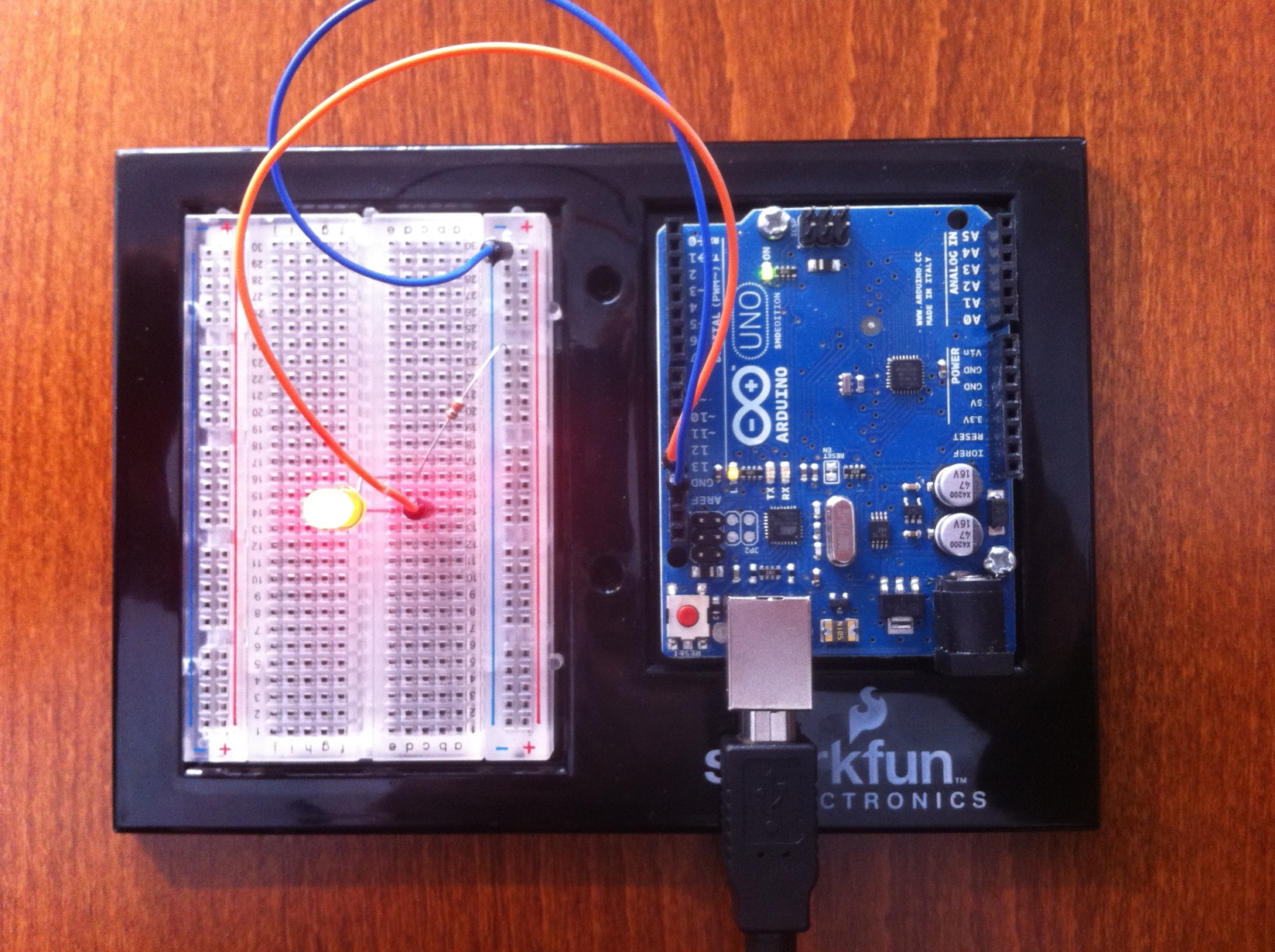
  • Mount your LED between Pin 13 and GND

    • Don’t forget the 330Ω resistor for a 1.7V LED with 10mA 🡪 (5V-1.7V)/0.01A = 330Ω
  • The program starts automatically after the download has been completed

    • The LED should switch on and off once per second

Part III CIP Arduino project

  • Modeling a reactive state machine using the CIP method
  • Generating C code for the state machine
  • Connecting the generated state machine code to the Arduino I/O
  • Downloading and testing to the Arduino board

CIP Arduino project

image28 image28

  • Switch to the Actifsource Perspective image29 image29
  • Select your project ch.actifsource.tutorial.cip.arduino in the Project Explorer
  • Select Configure/Add Actifsource Nature

image30 image30

  • Open Properties/actifsource/Resource Paths
  • Add the Resource Path asrc
  • Press Apply

image31 image31

  • Open Properties/actifsource/Built-in Dependencies
  • Add Builtin CIP
  • Add Builtin DATATYPE
  • Important: Press Apply

image32 image32

  • Open Properties/actifsource/Target Folders
  • Add the existing folder src as target folder
  • Add the BuildConfig CIP_C to the target src
  • Press OK

image33 image33

  • Select the Resource Folder asrc in the Project Explorer
  • Select CipSystem from the New Resource Tool in the Eclipse toolbar

image34 image34

  • Enter ch.actifsource.tutorial.cip.arduino as Namespace
  • Enter LampSystem as Name
  • Press Finish

image35 image35

image36 image36

  • Create a new Implementation named LampSystemImplementation in your LampSystem
  • Create a new ImplementationUnit named LampSystemUnit in your LampSystemImplementation
  • Create a new CipMachine in your LampSystemUnit
  • Reference the Cluster LampCluster in your CipMachine
  • Create a new CipShell in your LampSystemUnit
  • Reference the input channel Button
  • Reference the output channel Lamp
  • Create a new C_CodeOption named LampSystem_CodeOption using Content Assist (Ctrl+Space)

image37 image37

  • Configure the newly created LampSystem_CodeOption
  • Set useInterface to useMessageInterface
  • Set usePostFix to InitPostFix
  • Set enable_PENDING_Information to true
  • The code for your CIP system is now generated in the target folder src
#include <avr/io.h>
#include <util/delay.h>
#include "sLampUnit.h"

#define LED_PIN     PB5   // LED connected to PB5 (Arduino Pin 13)
#define BUTTON_PIN  PB4   // Button connected to PB4 (Arduino Pin 12)

void AI_LampUnit_C2_Dark() {
  PORTB &= ~_BV(LED_PIN); // Turn LED OFF
}
void AI_LampUnit_C2_Bright() {
  PORTB |= _BV(LED_PIN);  // Turn LED ON
}
void iMSG_LampUnit() {
  OUT_LampUnit.C2_Dark = AI_LampUnit_C2_Dark;
  OUT_LampUnit.C2_Bright = AI_LampUnit_C2_Bright;
}

int main(void)
{
  if (!fINIT_LampUnit()) {return 1;} // init cip
  // Set LED_PIN as an output
  DDRB |= _BV(LED_PIN);

  // Set BUTTON_PIN as an input and enable internal pull-up resistor
  DDRB &= ~_BV(BUTTON_PIN);  // Configure as input
  PORTB |= _BV(BUTTON_PIN);  // Activate internal pull-up (idle state = HIGH)

  int oldbuttonState = 0;

  while (1) {
  int newButtonState = PINB & _BV(BUTTON_PIN); // read button pin
  TRG_LampUnit.TICK_();
  // ticking time
  if(oldbuttonState!=newButtonState && newButtonState==1) {
    IN_LampUnit.C1_Push();
  }
  if(oldbuttonState!=newButtonState && newButtonState==0) {
    IN_LampUnit.C1_Release();
  }

  oldbuttonState=newButtonState;

  while (TRG_LampUnit.PENDING_.ANY_) {
    TRG_LampUnit.STEP_();
  }
    delay_ms(4);
  }

  return 0; // Never reached
}
  • Rewrite your main.c as shown above
Info

Your code is probably not linking if you named your file main.cpp instead if main.c

image38 image38

  • Download your code to the Arduino

    • Select your project SimpleProject in the Project Explorer
    • Press the AVR download button in the Eclipse toolbar image26 image26

image39 image39

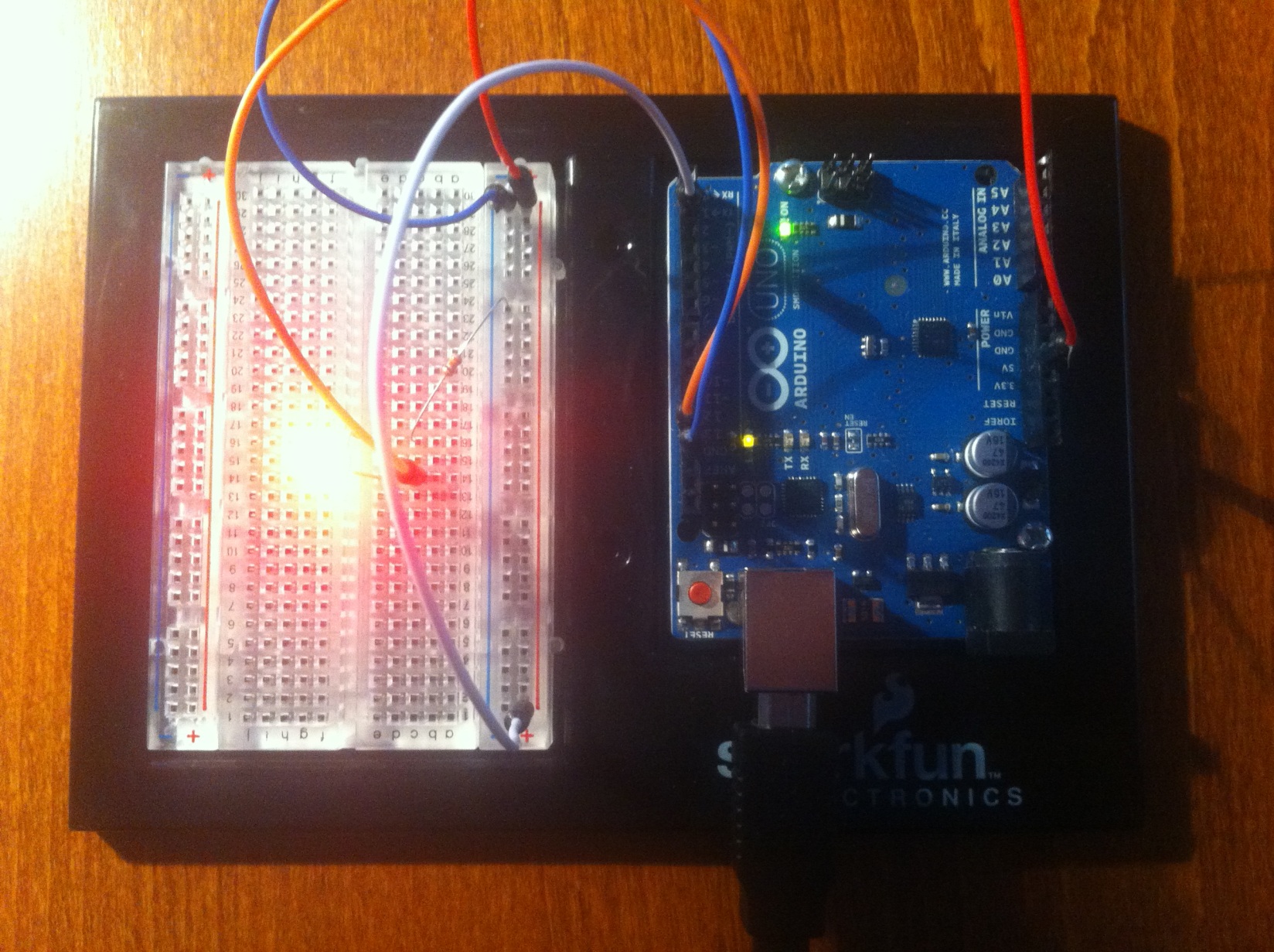
  • We built a lamp with a delayed off switch

    • Pin 2 on GND means Button is released
    • Pin 2 on 5V means Button is pressed
  • Start while Button is released

  • Press Button 🡪 Light should switch on

  • Release Button 🡪 Light should switch off with delay

    • Tune with the delay function of your timer and the delay_ms() call in the main.c

actifsource-point-large