- Setup a new C/C++ project
- Write a very simple code which switches an LED on and off
- Compile the project including the Arduino core
- Download to the Arduino target and run
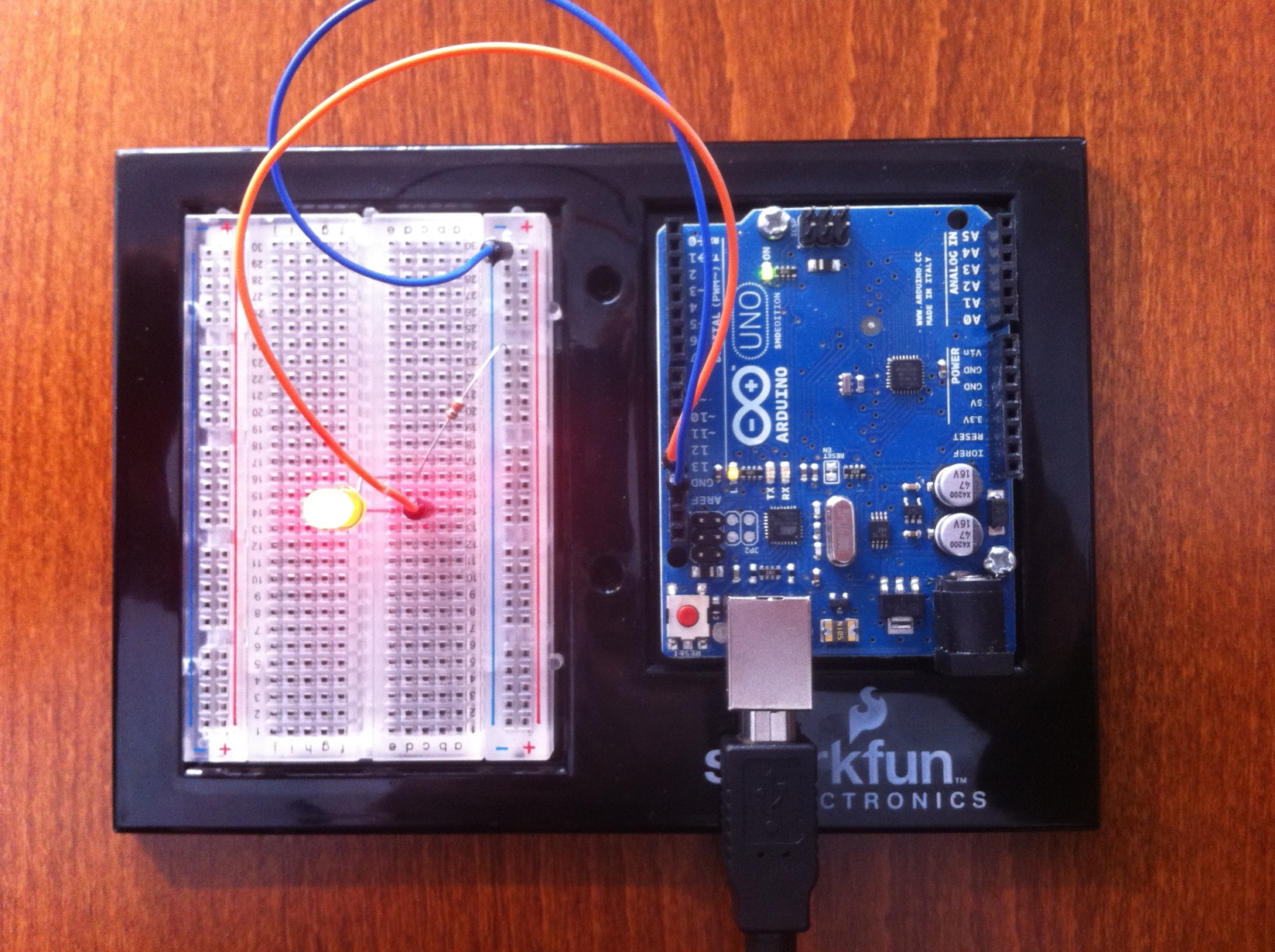
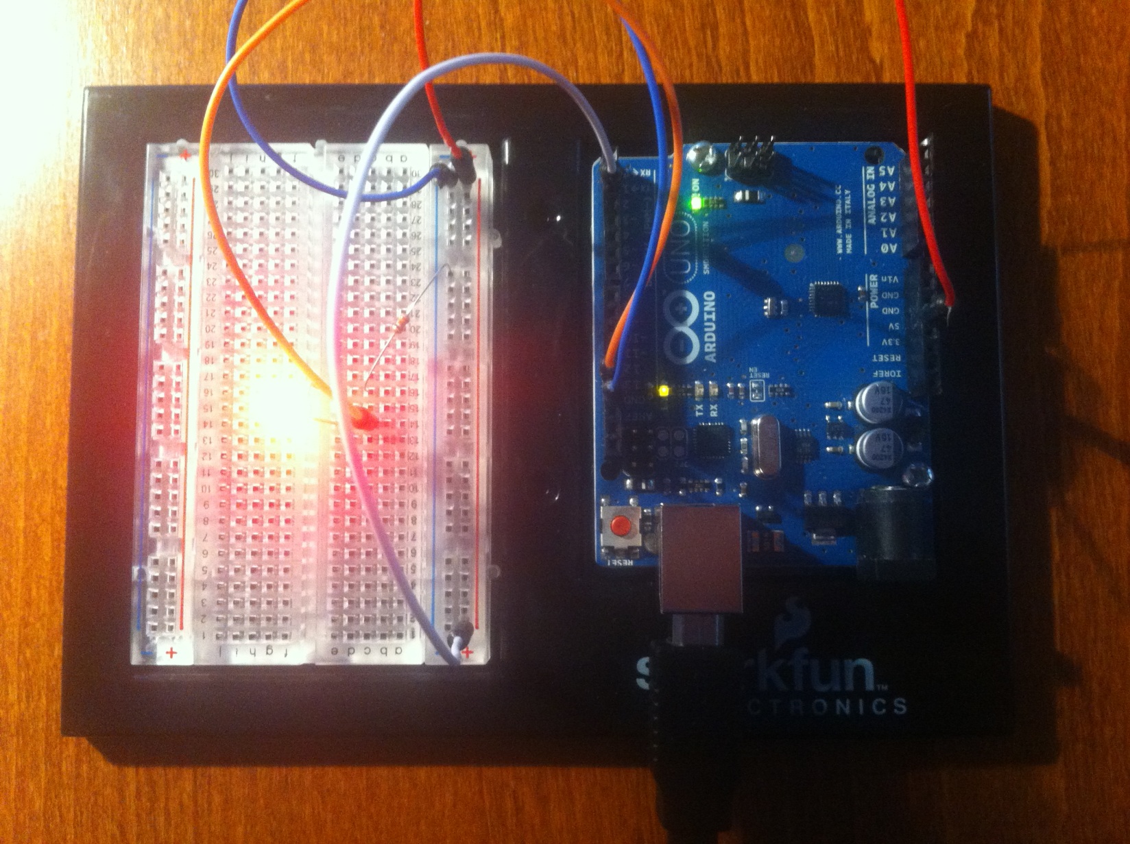
Simple Arduino project

-
Create a new C++ Project
-
You have to create a C++ project even if you plan to write C code since we have to compile the Arduino Core
-
If you can’t create a C/C++ Project you have probably not downloaded the Eclipse for C/C++ Developers

- Create a new C++ project named
ch.actifsource.tutorial.cip.arduino
- Choose AVR Cross Target Application
- Choose the AVR-GCC Toolchain
- Click Next

-
Do not create a Debug Version
-
The debug code is too large to fit on the Arduino Uno
-
See boards.txt for the maximum code size
- uno.upload.maximum_size=32256 for this example
-
Click Fish
-
Open the C/C++ Perspective if you are asked or open it manually in the upper right corner


- For the newly created
ch.actifsource.tutorial.cip.arduino, choose Properties (Mouse-Click-Right on the project)
- Select C/C++ Build
- In the Build Variables Tab, enter the following variables:
- AVRDUDEOPTIONS, set to
-p atmega328p -c arduino -P/dev/ttyUSB0 -b 115200
- AVRTARGETFCPU, set to
16000000
- AVRTARGETMCU, set to
atmega328p
- Click Apply

- In the Environment Tab, enter the following variables:
- AVRTARGETFCPU, set to
16000000
- AVRTARGETMCU, set to
atmega328p
- Click Apply

- In the Settings Tab, set AVRDude to true. This will automatically download the program to the attached board
- Click Apply

-
This step is only needed on Windows
-
SimpleProject/Properties/C/C++Build/Settings/AVR Compiler/Directories
-
Set Include Path C:\arduino-1.0.3\hardware\tools\avr\avr\include
-
Set Include Path C:\arduino-1.0.3\hardware\arduino\cores\arduino
-
Set Include Path C:\arduino-1.0.3\hardware\arduino\variants\standard
- See boards.txt (uno.build.variant) for your variant (standard for this example)
-
Click OK

-
Do the same again for SimpleProject/Properties/C/C++Build/Settings/AVR C++ Compiler/Directories
-
Set Include Path C:\arduino-1.0.3\hardware\tools\avr\avr\include
-
Set Include Path C:\arduino-1.0.3\hardware\arduino\cores\arduino
-
Set Include Path C:\arduino-1.0.3\hardware\arduino\variants\standard
- See boards.txt (uno.build.variant) for your variant (standard for this example)
-
Click OK

- Create a new folder
src in the project

- Create a new file
main.c in the folder src
#include <avr/io.h>
#include <util/delay.h>

#define DELAYTIME 500  // 500ms Verzögerung

int main(void)
{
  DDRB |= _BV(DDB5); // Setze Pin PB5 (Arduino LED) als Ausgang

  while (1) {
    PORTB |= _BV(PORTB5);  // LED einschalten
    _delay_ms(DELAYTIME);  // Wartezeit

    PORTB &= ~_BV(PORTB5); // LED ausschalten
    _delay_ms(DELAYTIME);  // Wartezeit
  }

  return 0; // Dieser Punkt wird nie erreicht
}
- Write a very simple Arduino program in the file
main.c as shown above
- If you enabled Build on resource save (Auto build) in Project/Properties/C/C++Build/Behaviour before, the code should now be built
- You can also build manually by pressing Project/Build All (Ctrl+B ) or the build button in the Eclipse toolbar

Info
Your code is probably not linking if you named your file main.cpp instead if main.c

- Download your code to the Arduino